A few months ago, I found this Hacker News post about the AirGradient DIY Air Quality Monitor. I had already been considering buying an AirThings Wave Plus sensor to monitor my home's CO2 levels, but the high price and limited 'ownership' of the data coming from it turned me off.
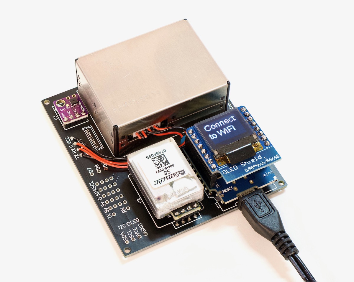
So I built two AirGradient DIY air quality monitor boards (see above), and integrated them into my Prometheus + Grafana home monitoring setup I've been using to monitor other things in my house:
I emailed Achim, the founder of AirGradient, and took him up on his offer for free PCBs if I paid the shipping cost. A couple weeks later I received two fresh PCBs from Thailand. If you don't want to wait for the shipping, or want to make a bunch of sensor boards, you can also download the Gerber files from the AirGradient DIY page and have your own PCBs made.
Update: It looks like AirGradient now offers DIY Air Quality Sensor kits that you can purchase, which include all the sensors in one package. That definitely makes sourcing the parts easier!
Parts and Cost
As suggested on the DIY sensor page, I ordered all the components through AliExpress. The prices there were often half what they were from any US supplier, though shipping was a different matter—even though shipping direct from China was a pittance (free, in fact, for most of the components), it took at least a month for all the various components I ordered to arrive.
With most US suppliers, I could get 2-3 day shipping; but, for one example of the price difference: the same SenseAir S8 that cost $30 from AliExpress costs $60 from a US distributor!
Here's the list of all the prices I paid, to get an idea of the total cost (all prices in USD):
- Shipping for 2 free AirGradient PCBs from Thailand: $9
- SenseAir S8 CO2 Sensor: $28
- WeMos D1 Mini: $3.11
- D1 Mini OLED Shield: $4.30
- SHT30 Temperature and Humidity Sensor: $4.42
- Plantower PM2.5 Sensor: $13.80
Note that when I went to order the Plantower sensor, it was out of stock, so I picked one up from Amazon instead (DEVMO PMS5003 PM2.5 particle sensor) for $35. Steep price difference, but hey, at least I got it!
All-in, the components for this project cost between $60-80, depending on where you get your parts.
Assembly and Soldering
AirGradient's DIY assembly guide is already pretty solid, but if you want even more detail, watch my video on the DIY air quality monitor, where I show each step of the assembly:
The hardest part is the stripping and soldering of the tiny stranded wires that come with the PM2.5 sensor, but I made short work of it with a little Adjustable Wrench Stripper that's designed for stripping smaller-gauge wires.
3D Printed Case
AirGradient also offers a 3D-printable case and wall mount bracket, which seem to fit together well (if not a bit tight) and hold the board in the best orientation for the various sensors to work well.
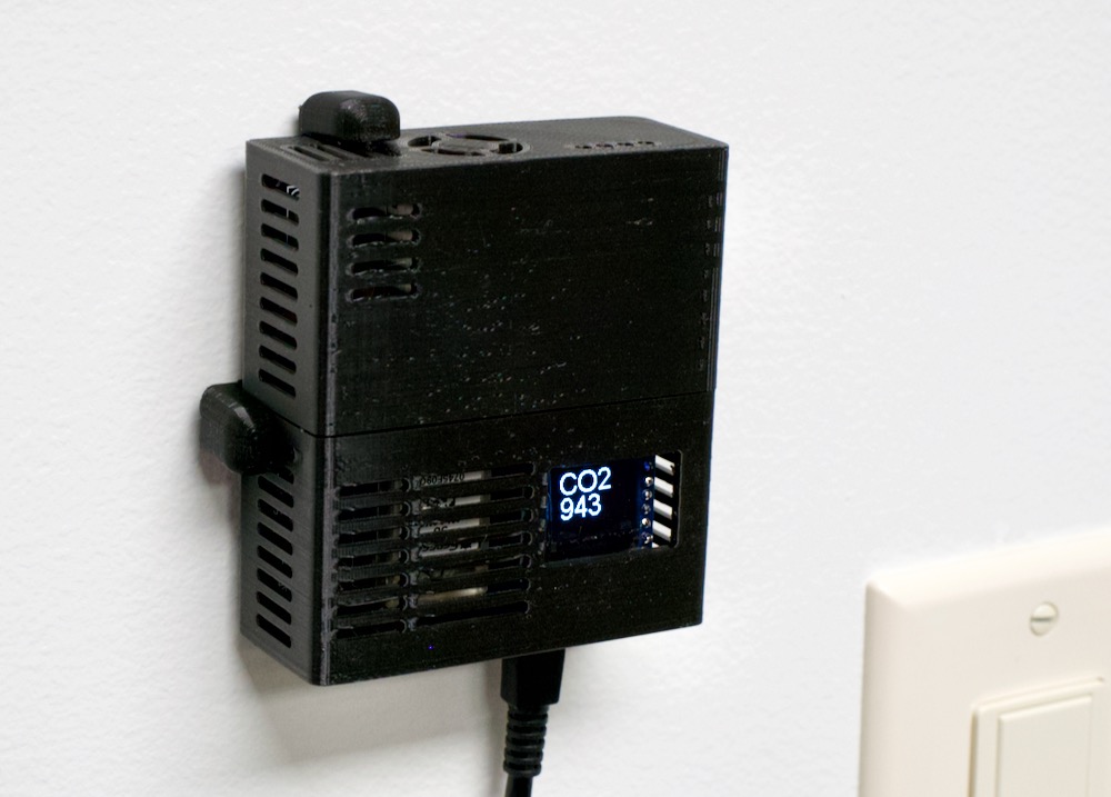
The case is well-ventilated, and my only complaint is the natural convection causes very-slightly-warmed air from the WeMos D1 and CO2 sensor to pass over the temperature and humidity sensor on the top, meaning those readings are always a bit higher than ambient—at least in my office.
Flashing the firmware / AirGradient software
With the hardware put together, I followed the guide for setting up the software on the WeMos D1 Mini. The guide was decent, but I figured I'd go through every step in detail here, especially since I changed a few things to make it easier for me to get air quality data on my local Prometheus instance instead of on AirGradient's servers.
First, the easiest way to flash an ESP8266 is to Install Arduino IDE. On my Mac, since I use Homebrew, it was a simple matter of:
brew install --cask arduino
Then you have to configure Arduino IDE so it can manage an ESP8266 board like the WeMos D1 Mini:
- Open Arduino IDE
- Open the Preferences window
- Add
http://arduino.esp8266.com/stable/package_esp8266com_index.jsonto "Additional Boards Manager URL". - Open "Boards Manager..." from Tools > Board menu.
- Search for the "esp8266" board and install it's latest version.
- Select "LOLIN(WEMOS) D1 R2 Mini" from the Tools > Board > ESP8266 menu.
Optionally, you can test your setup by uploading the Blink sketch:
- Open File > Examples > 01.Basics > Blink.
- Make sure "LOLIN(WEMOS) D1 R2 Mini" is selected in the Tools > Board menu.
- Go to Tools > Port and select the USB serial port where the ESP8266 is plugged in (in my case, "/dev/cu.usbserial-210")
- Click the 'Upload' button (right arrow) to upload the sketch to the board.
After a minute or so, the blue onboard LED (which is under the OLED shield) should start blinking continuously.
Now it's time to flash the AirGradient software to the WeMos D1 Mini (note: If using the sketch from my airgradient-prometheus project, follow it's README instead of these steps):
- Go to Tools > Manage Libraries...
- Search for "AirGradient", and install the latest version.
- Choose "C02_PM_SHT_OLED_WIFI" from the File > Examples > AirGradient Air Quality Sensor menu.
- Install the libraries suggested at the top of the file via Tools > Manage Libraries...
- WifiManager by tablatronix
- ESP8266 and ESP32 OLED driver for SSD1306 by ThingPulse
- Optionally enable WiFi at this point by setting the
connectWIFIvariable totrue. - Upload the sketch to the ESP8266.
- After a minute or so, the OLED display should read "Init", then after a delay it will start printing PM2.5, CO2, and Temperature/Humidity numbers, in sequence.
I actually forked the C02_PM_SHT_OLED_WIFI example and maintain my own copy, which works with my local Prometheus instance. You can see that project here: airgradient-prometheus.
Getting data into Prometheus
If you just set connectWIFI to true, it would send data to AirGradient's servers (defined in the the APIROOT variable). The payload is simple JSON, so I wrote a script that logs the data from the sensor, and another script running at a /metrics endpoint, which returns the latest data when Prometheus requests it.
Those PHP scripts, along with a README file that explains how to run them in a tiny Docker container, are available in my open source AirGradient Prometheus Exporter project on GitHub.
To get the AirGradient board to send its data to my Internet Pi—where I chose to run the AirGradient exporter—I changed the APIROOT in the Arduino sketch to http://geerli.net:9926/.
I actually have two air quality sensors running now—I set the first one to port
9925, and the second to port9926, and my Internet Pi has two Docker containers running the individual exporter for each port.
I flashed the device using Arduino IDE, then when it showed 'Connect to WiFi' on the screen, I connected directly to the device's 'AIRGRADIENT' WiFi hotspot, then my Mac popped up the connection screen, and I added the credential to connect it to an 802.11 b/g/n access point on my network.
After a few seconds, it connected, then every 9 seconds or so, the sensor POSTS something like the following data to the Raspberry Pi:
10.0.100.74 - - [06/Jul/2021 12:54:59] "POST /sensors/airgradient:1995c6/measures HTTP/1.1" 200 -
INFO:root:POST request,
Path: /sensors/airgradient:1995c6/measures
Headers:
Host: geerli.net:3939
User-Agent: ESP8266HTTPClient
Accept-Encoding: identity;q=1,chunked;q=0.1,*;q=0
Connection: keep-alive
content-type: application/json
Content-Length: 56

Body:
{"wifi":-51,"pm02":5,"rco2":1605,"atmp":32.60,"rhum":37}
The script running in the Prometheus Exporter then stored the data in a file, and when Prometheus calls the /metrics endpoint on the same port, the metrics are transformed into a format Prometheus can understand.
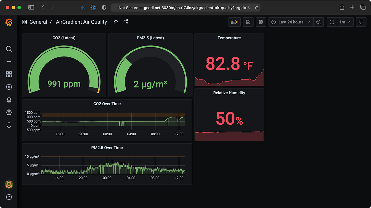
Finally, once I had all that data, I built dashboards in Grafana to display the air quality sensor data over time—one for the board in my basement office, and one for the board upstairs in the main part of my house:
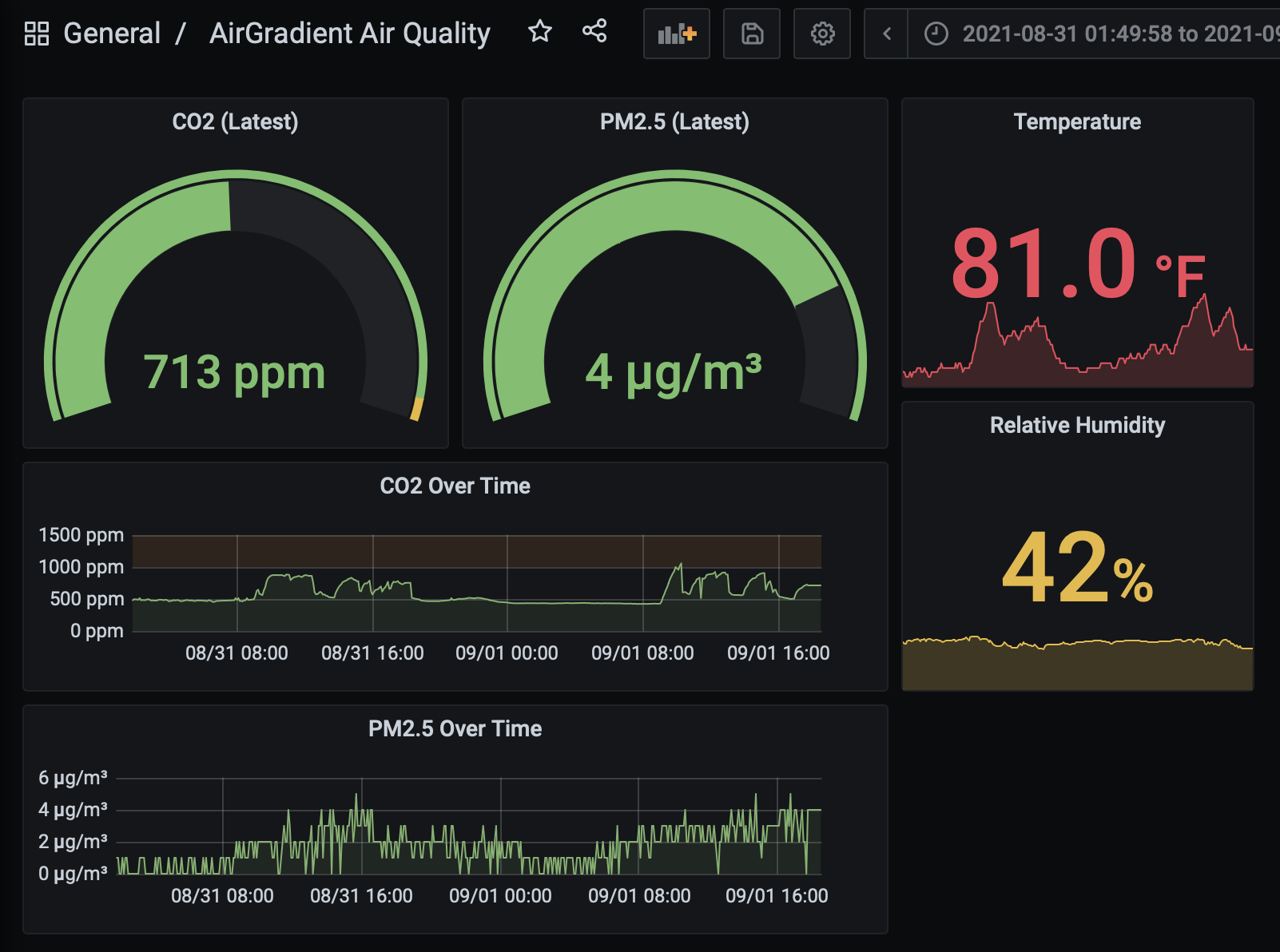
It's easy enough to identify when I was in the office if you look at the CO2 graph above—and I can imagine if there were more people crammed into that 12 sq ft space, it would spike even higher!
The levels top out around 900 ppm when I have my air vent open in the office, but I've observed them going beyond 3000 ppm when I closed the vent and was in the office for more than a couple hours at a time. So... moral of that story is to make sure you have some fresh air circulation!
Conclusion
The sensor package and board layout aren't perfect; the temperature and humidity sensor, in particular, is always a few degrees (F) higher than other known-working thermometers display. And the SenseAir S8 takes a couple weeks before its self-calibration routine finishes—until that's done, CO2 levels will likely show as being at least 200 ppm higher than they actually are.
But after a few weeks, and after adding in a manual temperature adjustment to compensate for that sensor's inaccuracy, the AirGradient has been a very stable and helpful addition to my home environment monitoring.
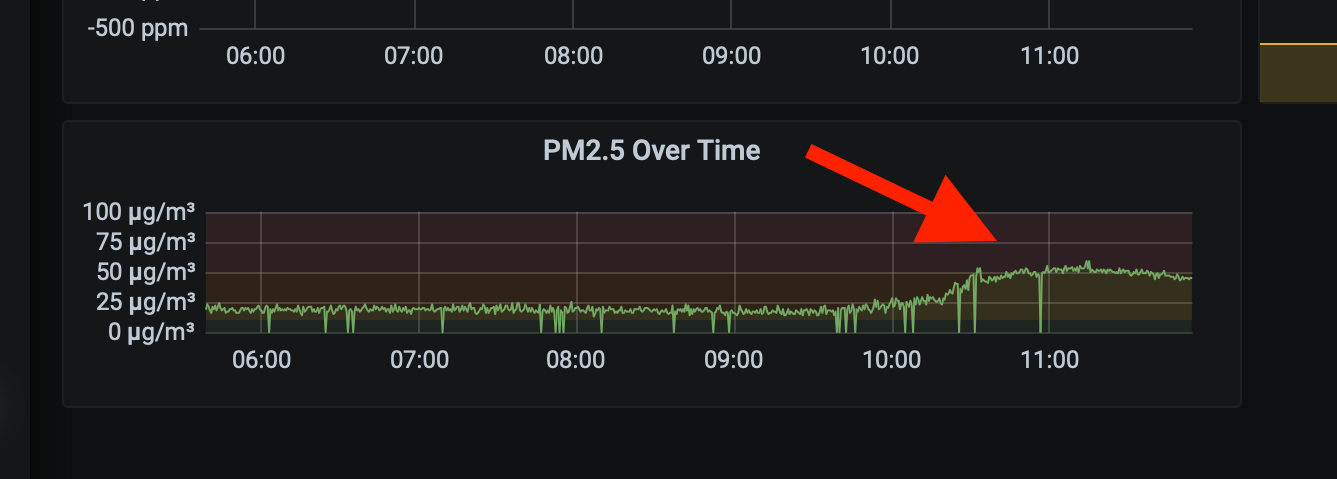
In fact, after having my basement windows replaced, the PM2.5 sensor indicated particulates were above 50 μg/m³, which is an actionable level—if I hadn't opened a window with a fan circulating extra outside air, that level would've remained high for many hours, exposing my family to whatever tiny bits of dust and chemicals lingered in the air.
If you want even more detail about the build process, check out my YouTube video on the AirGradient DIY Air Quality sensor.
Comments
How does calibration work? How can you be confident it has accurate results?
If you want lab-grade results, you'd need the right testing equipment (see SenseAir's website), but I'm okay with consumer-grade. So for that, my informal process is to place multiple sensors (ideally from different vendors—e.g. TemTop + my DIY sensor + another if I have it) next to each other a foot or so away in a couple places for a couple days, and compare the results.
If they're within a close range, they're accurate, if not, they're not, and they may need adjustment.
For the temperature sensor on the DIY board, it is definitely 5-10°F higher than ambient, so I'll need to figure out a better solution for its placement.
For the PM2.5 and CO2 sensors, the data between the TemTop and my two DIY boards is very close (usually < 2% difference, e.g. TemTop reads 820 ppm, DIY reads 814 ppm). But note that the SenseAir S8, at least, requires at least a couple weeks to self-calibrate—it does that I think by trying to get a baseline, and that baseline it calibrates to is somewhere around 440 ppm? Not quite sure, but I remember reading about it in a spec sheet and thinking it was a little above my pay grade.
There's a way to force-calibrate it, too, if you have a stable environment where you can do that.
It's important to note that (especially) the CO2 sensors have quite a wide range (usually 3%, 50 PPM) and will auto-calibrate, depending on the chip that's on them. You can sometimes turn that off.
These types of NDIR CO2 sensors (single chamber) are also not meant for 24/7 occupancy, they will try to reset to ambient (usually 400, or 425) once a day, a week, or some other interval by default because they don't have a second sealed chamber to calibrate on. If you see them gradually rising over time and then see sharp drops back to 400-ish that's why. Also note that the CO2 sensor is temperature sensitive which is one of the reasons it needs to calibrate that often.
For your temperature sensor; using the BME280 on a breakout for temperature will always give high results, you might want to incorporate a DS18B20 specifically for temperature sensing, it's THT and you will be able to position it further from other components.
For what it's worth, I heeded your warning about the SHT30 reading high and how you thought it was because of its placement relative to the D1. Rather than soldering it to the board, I ran three-inch wires to move it toward the bottom, at the same level as the D1 when wall-mounted. Further, I don't have a 3D printer, so it's sitting open right now.
I've been watching it for two days now alongside two other thermometers. It's consistently reading somewhere around 5 degrees higher than the others, which agree with each other.
While you might be catching a little heat from the D1, I think there's something else going on here too.
This is great! I did something similar with the AirThings Wave Plus. I know you were concerned about the ownership of the airwave plus data, but the cloud functionality relies on the phone app to upload to their servers. I use a raspi with a bluetooth dongle to extract the data using their python reader https://github.com/Airthings/waveplus-reader. This makes it so the data stays within my house. I expose that data as a prometheus endpoint and have a very similar looking dashboard - https://i.imgur.com/OZFyB0M.png . I am using a SDS011 Nova PM Sensor for the particulate. Radon sensor was my highest priority when making this set up, because I wanted to make sure my Radon suppression system was functioning correctly
Thanks, Jeff, for sharing this project! I was also wanting to put together an air quality sensor array, so this was perfect timing. To keep the data local to my network, I'm hacking the AirGradient code to use MQTT and send the data to a Mosquitto MQTT Broker on a RPi4 running Homeassistant. From there, I can use your Grafana interface (nice job!) to display the results.
Another hack I'm going to try is to use an ESP32 packaged in a WEMOS D1 Mini format. It's slightly wider, but I'm hoping to squeeze it on the board (https://www.wemos.cc/en/latest/s2/s2_mini.html) so that I can add other sensors like an MQ-4 (natural gas) and MQ-7 (carbon monoxide) using the additional ADC pins on the ESP32. The Bluetooth on the ESP32 also provides the future possibility of connecting it to sensors like an Inkbird and acting as an MQTT gateway (example: https://github.com/runningtoy/InkBird_BLE2MQTT). I'd love to hear if someone has already done this with an Inkbird IBS-TH1.
Stuart could you share the code changes you made to support MQTT and HomeAssistant? I'm wanting to get it reporting data to HomeAssistant as well, but I'm new to MQTT and unsure how that would work.
Or Jeff, are you still considering HomeAssistant? It has been great for me, and always looking for more integrations to it.
I adapted Jeff's scetch for MQTT reporting myself.
https://gist.github.com/erijpkema/e2b896155990768f4d53f4734e8d41dd
Do you know if we could swap out the Plantower PM2.5 PMS5003 senor to something else like the PMS9103M? I have not been able to find a clear comparison of the different sensors and what would be best for a house.
Hello. Have you find out how to make it work with PMS9103M? I have got one recently, but seems like all the libraries are for PM ending with 03, and this one is ending with 03M and Im worried if that's ok. If you can answer, please respond to [email protected] :)
Now sure what your data ownership issues are, but you can read directly from the device, there's even an example graphana dashboard if you want to avoid using a cloud. The data is yours to do with as you wish.
It was my understanding you had to use an app to do the initial setup of the AirThings devices, but if you can do it completely standalone, separate from an Internet connection, that would make my opinion a lot more favorable! Though it's still quite pricey.
It seems to me that perhaps if you rotated the entire sensor assembly 90 degrees counterclockwise, the convection airflow passing over the temperature sensor would be mitigated at least somewhat. Seems like an easy fix, you'd just have to rotate the output on the OLED display in your Arduino sketch. I think that's possible by simply adjusting the parameters during initialization of the OLED library. Does this make sense?
By the way, it would be awesome if you combined this sensor data with a controller on your furnace fan (separate from the heating and cooling) or another actuator (perhaps controlling a window opener or a fan to the outside, or both) to automatically keep the particulate and CO2 levels low. If your furnace has a HEPA filter, it'll handle the particulates, and the air flow should handle the CO2 buildup. The way I see it, you could manually calibrate a PID controller based on taking readings periodically. It may be possible to do this automatically over a certain period of time since you're collecting time-series data on your rpi. It would neat to use some basic time-series predictive modelling to give proactive notifications about participate and CO2 levels going high. This link has a super simple tutorial for Python that you could walk through and apply on the data coming straight out of your grafana instance:
https://www.bounteous.com/insights/2020/09/15/forecasting-time-series-m…
Walking through this stuff would make for a great YouTube video, with a fairly minimal amount of burden I think.
I'd try connecting the SHT sensors with wire and just letting them dangle at the bottom of the case or near a vent hole, but it's probably 50/50 between locally generated heat throwing off the results and, well, there's a reason they're $2.55 from alibaba. Although digikey's prices get similarly reasonable at the thousand-per unit price, so it's not obvious that they're chips that fell off the back of Sensiron's QC truck in Shenzen.
I have been looking for a DIY temperature and humidity sensor that incorporates a Raspberry Pi for a while. Thank you for including this within the internet pi project and making it a simple switch to flip. I have the parts on order and will try building this when they come in.
Good luck, hope it works!
What is the noise level like on the fan in the PM2.5 sensor? Would it be noticeable near a bed at night?
No, I can't hear that fan at all unless I'm a couple inches from it in a very quiet room. Upstairs I've never been able to hear it at all!
Thank you! I have been wanting to monitor CO2 in the bedroom but I didnt want any extra noise.
Would you be interested in gathering a bunch of pre-orders of unassembled kits and then buying a bulk order to save on pricing? I’d pre-pay for a few kits myself — and I’m sure there are other followers on your various social media channels that would do the same. I’d offer to organize it myself but I’m just swamped.
Looks like AirGradient is selling complete kits: https://docs.google.com/forms/d/e/1FAIpQLSdJxizUbGHxDAOmE7dWs0ChK2b0Y4L…
Hi, great video - pleasure to watch that! Have you had any chance to try something more what is more like a plug-n-play I mean some usb dongle (supported by rpi or openwrt perhaps)?
Adafruit SCD-30 - NDIR CO2 Temperature and Humidity Sensor - STEMMA QT / Qwiic. It is a I2C controller that will plug into an RPI easily. Will also work with pretty much any Microcontroller known to man.
https://www.adafruit.com/product/4867
How would you go about using the spare D pins to add additional sensor (ozone, carbon monoxide, etc)?
How simple would it be to adapt the code to spit other sensors (Ozone, carbon monoxide etc) data across if we attached them to some of the spare digital pins?
I'm an Arduino guy and would like to have the home monitoring bits.
would it be too much to ask to have a video showing the noobiest, noob verion of how to do the Pi stuff ?
I did make a simple temperature/humidity on an WEMOS as an AP so I could long on and read the data, but I would like to get the data logging and graphs.
I've been looking at indoor air quality after doing some weatherization, and starting to shop around for new HVAC gear.
I have a few ESP32 boards with various sensors (the Sensirion SCD4x for CO2), but I've found the Awair Element to be the winner. It looks great, priced pretty reasonably, and offers local-only (no internet access needed) API.
https://www.getawair.com/products/element
Info about the local API here:
https://support.getawair.com/hc/en-us/articles/360049221014-Awair-Eleme…
I have two of them, and a couple of other CO2 sensors. It's been eye opening. CO2 levels pretty rapidly build up in my house, so definitely going to look at getting an ERV with a new HVAC system.
At $300 for each of the elements you can build 5 of these sensors and distribute them around the house. One thing that becomes apparent by measuring the outside and inside air simultaneously is that it won't matter how much you exchange air if the PM2.5 and CO2 levels are similar to indoors.
Thanks again for the post Jeff - I've built five of these and put them in various places in the house using the pull request to allow for the scrapable metric end-point with great results - now just to figure out some of the nuances with Prometheus and Graphana to get the dashboard to look right.
Thank you so much Jeff. Since being made aware of this project, I bought a kit and put it together a few days ago. Now looking forward to figuring out how to integrate it with my HomeAssistant so I can track it with the rest of my local home data.
Excellent! Hope it works great for you. One way to get it in is using ESPHome for the sensor—it seems like that would be the quickest path to get it integrated with HomeAssistant.
Thanks for the lead on ESPHome. I've been playing with it all week and now I have it setup to recreate the AirGradient config, sending to their web server as well as HomeAssistant. It has been incredibly fun and now I've ordered more D1 mini devices for other home projects, like my monitor Ambilight
https://github.com/MallocArray/airgradient_esphome
Your project looks great! Love the simplicity of ESPHome, and I'll definitely be testing it out now. See my issue for testing: Investigate use of ESPHome instead of a custom sketch.
So I am having trouble getting the sensor to send the data to the dashboard. I have the internet pi setup and i can see the internet speeds and pi hole is working but nothing from the sensor is making it there. The sensor is working great on the led screen, not sure how to find out what i am doing wrong!
You can take a look at a video made by DB tech "Docker Dashboard Using Grafana, Prometheus & Node Exporter". It's easier to follow.
After setting it up without the node exporter (not what we need), follow the instruction on Jeff's blog by putting the code to your prometheus.yml. At this point you should be able to see your Air Gradient server on prometheus. Finally, setup a dashboard on Grafana admin page.
When do you think you'll be publishing a tutorial on how to get the data into Grafana/Prometheus? Also I'd love to be able to get this data into my Synology Nas as I already have Grafana and Prometheus installed there, I just need steps on how to get the data from my AirGradient into it.
Thanks for the great work.
There's actually a PR in to my project repo to make it so the AirGradient acts as a webserver and Prometheus can pull data straight from it—I plan on updating that soon so it is easier to integrate into other Prometheus setups too: https://github.com/geerlingguy/airgradient-prometheus/pull/4.
I'm getting some very mixed results with my CO2 sensor while trying a couple of different power sources for powering the board. So far I've tried:
- My laptop's USB port(s).
- A USB hub (which is connected to the laptop).
- 3 USB chargers (two that go up to 5v/2A, one that goes up to 5v/1A).
- A power bank.
Depending on the input voltage that is being fed into the CO2 sensors I get back results in different value ranges or in the worst case scenario the sensor errors out and always reports 0 ppm. Specifically, using the G+ and G0 pins, I've measured the input voltage that goes into the CO2 sensor when connected to each power source and these are the results I got:
- Laptop USB ports: 4.83v - 4.86v -> 0ppm, fatal error (bit 1) and algorithm error (bit 3) of MeterStatus are set.
- The 2 5v/2A chargers: like above.
- Power bank (over 75% charge): like above.
- USB hub and 5v/1A charger: 4.66v - 4.70v and 4.66v - 4.73v -> difference of around 300PPM between value ranges depending on which power sources I use, errors bits not set.
- Power bank (under 75% charge): I forgot to measure the input voltage (will do once it gets low enough again). Error bits no longer set, seems to report the most accurate values (I left the sensor outside and it was registering between 350-420ppm). While inside, it registers values around 600PPM lower than in the case of the USB hub and the 5v/1A charger.
According to the spec sheet it should handle any voltage between 4.5v and 5.25v so I don't really know what to make out of these results. Could it be that my unit is busted?
On a unrelated note, checkout ESPEasy. It's a firmware that you flash on the board, it offers a web interface for configuring devices (including the OLED display) and even has options for publishing using MQTT, UDP, (Generic) HTTP (and many more). Feels much nicer and less like a hack compared to AirGradient's Arduino code.
My screen isn't turning on. But i can get the blink sketch to work
nvm it was...plugged in backwards
I had the same problem at first, turns out I'm a total noob at this and needed to resolder some of the pins
Many thanks for this Jeff.
For other Mac users it might be worth mentioning that you can get into a real mess with old versions of Homebrew. I did.
I got bizarre errors when trying to install cask.
The solution was to delete the old version and install from scratch.
I also had a problem with my router not wanting to allow my board to connect. Solved this by hard coding as follows
#define WIFI_SSID "YOUR WIFI NETWORK SSID"
#define WIFI_PASS "YOUR WIFI PASSWORD"
WiFi.begin(WIFI_SSID, WIFI_PASS);
Yes. I know this is not a good solution. However, at least I could get on with the rest of the project while I figure it out.
Great project! Thanks for doing this. I ordered a kit and built it to help me monitor my shop air quality and have since ordered two more kits that I recently received and have to put together soon. I also got three blank boards to populate later. I think I'll probably install 5-6 of these in various parts of the house. We have a three zoned HVAC walkout and I've been searching for a good way to monitor humidity throughout the house with a central repository for the data. Next I'll have to figure out how to collect the data from multiple units.
Any suggestions for a good learning resource for Prometheus andGrafana?
Trial by fire, and reading and re-reading the docs :)
That's basically how I learned, though I should probably spend a little more time discussing them at some point!
Im having some problem uploading data from airgradient to the pi, i folloved the guide and the airgradient board is now connected to wifi but if i try using the command curl "http://airgradient-ip:9926/metrics" i get a connection refused message, i've also tried a telnet on port 9926 and i get no response. is there something i might have misconfigured?
also i noticed that if i reupload the sketch it will reconnect to wifi without asking the password, is there a way to reset the wifi credentials?
did you replace the airgradient-ip part of the url with your actual ip? something like 192.168.1.12?
Thank you Jeff!
I successfully built the board, and fed the data into Grafana. This is the first time for me to do soldering, so got it working on first trial was like winning a lottery.
I tweaked the code a little to sleep the OLED screen for 1 minute between each display cycle. In this way, the screen may last a bit longer.
One thing which annoys me is that the blue LED flashes every 5s. In a dark room, it's too bright. If my understanding is correct, it's controlled by D4 pin, which also connects to CO2 sensor to fetch data. Therefore, I can't turn it off.
A further improvement of the PCB would be adding a push button to activate the display and switch between readings. Even the Grafana works great, I still need to read from the board every now and then. Having the display to be always on or to sleep for 1 min between cycles are both not the best solution. I'm learning Arduino and PCB design to achieve this.
Looking forward to your comment on the idea.
Cheers,
Hank
Hi there. Great tutorial! I am unsure of what sort of AC power adapter to use. Will one for a Raspberry Pi with 5v/2A output work properly?
Yes, that would be perfect! I've found it needs at least a 1A 5V power adapter; anything less and it starts doing weird things (or won't boot at all).
I've build the sensor, is great. My office is in basement too and I was surprised about CO2 level.
The only difference thai I've implemented is in connection. As I use lot of other home automation sensors/actuators based mainly on Tasmota and using MQTT as a main network protocol, NodeRED for main event processing and InfluxDB as main data storage for measurements, I've wrote small PHP script sending the values via MQTT. The script resides in my existing nginx reverse proxy container - I just had add the PHP-FPM container and configure the nginx properly - especially rewrite rule for handling the sensor - and the future ones, as I got three boards from AirGradient, I plan to build and place the two at ground floor and upstairs.
Hey there. I have used the small connector and soldered all the pins/wires necessary for the PM2.5 sensor. It appears it won't upload my script when the PM2.5 is connected. I have to load the script, and then plug the PM2.5 to show me some data, otherwise, it appears WeMose D1 mini doesn't take any data, thru the USB connector.
ANY IDEA, WHAT CAN BE WRONG? I believe TX and RX pins have to be disconnected when uploading the script.
Hi Jeff, just wanted to say thanks for highlighting this kit and providing a straightforward guide. I was also interested in the kit, but wouldn't have ordered it and attempted the assembly if not for your video showing how simple it is.
I don't currently have any suitable hardware for an always-on home server with long-term storage, so I've set up my monitor to send data to Amazon Timestream using AWS IoT Core: https://github.com/ScriptSmith/daq/
It's actually pretty affordable at less than US$0.50 per month, and it should remain pretty cheap (subject to the whims of AWS) over a 10 year timeline as well.
I also switched to the platformio framework, which I found much nicer to work with than the Arduino IDE.
Great Project, have mine now running for about 2 weeks, but i have some weird issues with the CO2 Sensor, it reports to measure CO2 levels of over 65000ppm sometimes before it drops to normal levels or just reports the CO2 level with -1ppm.
might be a bad solder connection or a bad sensor, will have to invenstigate it further.
Bad sensor!!!
For folks that have built this - beware that the CO2 readings may be way off initially.
You can manually calibrate it with the guide on the Airgradient Forum.
Or you can wait 2 weeks, and it should calibrate itself (ensure that you leave the device outside for 10 minutes so it can get an accurate baseline to set to).
Hey!
I'm soldering this up now, with wires instead of the PCB. I'm a bit confused about the 5V connection to the humidity/temp sensor. It's operating voltage covers 2.4V to 5.5V, but wouldn't it be safer to power it with 3.3V given that it should communicate with the Wemos over I2C?
Hi Jeff
awsome work i build the sensor and it works. Very detailed video and instructions on the soldering part, but i struggle with the whole prometheus and grafana stuff... so right now it is offline and shows the data only on the screen... and i dont know where to start and what to do to show the data on my Pi... I have no clue about docker and all the other stuff and i wish you would make a tutorial video about all that...
Hi Jeff
When trying to load the package I am getting a weird error.
Arduino: 1.8.19 (Windows Store 1.8.57.0) (Windows 10), Board: "LOLIN(WEMOS) D1 R2 & mini, 80 MHz, Flash, Disabled (new aborts on oom), Disabled, All SSL ciphers (most compatible), 32KB cache + 32KB IRAM (balanced), Use pgm_read macros for IRAM/PROGMEM, 4MB (FS:2MB OTA:~1019KB), v2 Lower Memory, Disabled, None, Only Sketch, 921600"
C:\Program Files\WindowsApps\ArduinoLLC.ArduinoIDE_1.8.57.0_x86__mdqgnx93n4wtt\arduino-builder -dump-prefs -logger=machine -hardware C:\Program Files\WindowsApps\ArduinoLLC.ArduinoIDE_1.8.57.0_x86__mdqgnx93n4wtt\hardware -hardware C:\Users\REDACTED\Documents\ArduinoData\packages -tools C:\Program Files\WindowsApps\ArduinoLLC.ArduinoIDE_1.8.57.0_x86__mdqgnx93n4wtt\tools-builder -tools C:\Program Files\WindowsApps\ArduinoLLC.ArduinoIDE_1.8.57.0_x86__mdqgnx93n4wtt\hardware\tools\avr -tools C:\Users\REDACTED\Documents\ArduinoData\packages -built-in-libraries C:\Program Files\WindowsApps\ArduinoLLC.ArduinoIDE_1.8.57.0_x86__mdqgnx93n4wtt\libraries -libraries C:\Users\REDACTED\Desktop\Environment\libraries -fqbn=esp8266:esp8266:d1_mini:xtal=80,vt=flash,exception=disabled,stacksmash=disabled,ssl=all,mmu=3232,non32xfer=fast,eesz=4M2M,ip=lm2f,dbg=Disabled,lvl=None____,wipe=none,baud=921600 -vid-pid=1A86_7523 -ide-version=10819 -build-path C:\Users\bbwor\AppData\Local\Temp\arduino_build_369678 -warnings=all -build-cache C:\Users\bbwor\AppData\Local\Temp\arduino_cache_600031 -prefs=build.warn_data_percentage=75 -prefs=runtime.tools.xtensa-lx106-elf-gcc.path=C:\Users\REDACTED\Documents\ArduinoData\packages\esp8266\tools\xtensa-lx106-elf-gcc\3.0.4-gcc10.3-1757bed -prefs=runtime.tools.xtensa-lx106-elf-gcc-3.0.4-gcc10.3-1757bed.path=C:\Users\REDACTED\Documents\ArduinoData\packages\esp8266\tools\xtensa-lx106-elf-gcc\3.0.4-gcc10.3-1757bed -prefs=runtime.tools.mkspiffs.path=C:\Users\REDACTED\Documents\ArduinoData\packages\esp8266\tools\mkspiffs\3.0.4-gcc10.3-1757bed -prefs=runtime.tools.mkspiffs-3.0.4-gcc10.3-1757bed.path=C:\Users\REDACTED\Documents\ArduinoData\packages\esp8266\tools\mkspiffs\3.0.4-gcc10.3-1757bed -prefs=runtime.tools.python3.path=C:\Users\REDACTED\Documents\ArduinoData\packages\esp8266\tools\python3\3.7.2-post1 -prefs=runtime.tools.python3-3.7.2-post1.path=C:\Users\REDACTED\Documents\ArduinoData\packages\esp8266\tools\python3\3.7.2-post1 -prefs=runtime.tools.mklittlefs.path=C:\Users\REDACTED\Documents\ArduinoData\packages\esp8266\tools\mklittlefs\3.0.4-gcc10.3-1757bed -prefs=runtime.tools.mklittlefs-3.0.4-gcc10.3-1757bed.path=C:\Users\REDACTED\Documents\ArduinoData\packages\esp8266\tools\mklittlefs\3.0.4-gcc10.3-1757bed -verbose C:\Users\REDACTED\Desktop\Environment\libraries\AirGradient_Air_Quality_Sensor\examples\C02_PM_SHT_OLED_WIFI\C02_PM_SHT_OLED_WIFI.ino
C:\Program Files\WindowsApps\ArduinoLLC.ArduinoIDE_1.8.57.0_x86__mdqgnx93n4wtt\arduino-builder -compile -logger=machine -hardware C:\Program Files\WindowsApps\ArduinoLLC.ArduinoIDE_1.8.57.0_x86__mdqgnx93n4wtt\hardware -hardware C:\Users\REDACTED\Documents\ArduinoData\packages -tools C:\Program Files\WindowsApps\ArduinoLLC.ArduinoIDE_1.8.57.0_x86__mdqgnx93n4wtt\tools-builder -tools C:\Program Files\WindowsApps\ArduinoLLC.ArduinoIDE_1.8.57.0_x86__mdqgnx93n4wtt\hardware\tools\avr -tools C:\Users\REDACTED\Documents\ArduinoData\packages -built-in-libraries C:\Program Files\WindowsApps\ArduinoLLC.ArduinoIDE_1.8.57.0_x86__mdqgnx93n4wtt\libraries -libraries C:\Users\REDACTED\Desktop\Environment\libraries -fqbn=esp8266:esp8266:d1_mini:xtal=80,vt=flash,exception=disabled,stacksmash=disabled,ssl=all,mmu=3232,non32xfer=fast,eesz=4M2M,ip=lm2f,dbg=Disabled,lvl=None____,wipe=none,baud=921600 -vid-pid=1A86_7523 -ide-version=10819 -build-path C:\Users\bbwor\AppData\Local\Temp\arduino_build_369678 -warnings=all -build-cache C:\Users\bbwor\AppData\Local\Temp\arduino_cache_600031 -prefs=build.warn_data_percentage=75 -prefs=runtime.tools.xtensa-lx106-elf-gcc.path=C:\Users\REDACTED\Documents\ArduinoData\packages\esp8266\tools\xtensa-lx106-elf-gcc\3.0.4-gcc10.3-1757bed -prefs=runtime.tools.xtensa-lx106-elf-gcc-3.0.4-gcc10.3-1757bed.path=C:\Users\REDACTED\Documents\ArduinoData\packages\esp8266\tools\xtensa-lx106-elf-gcc\3.0.4-gcc10.3-1757bed -prefs=runtime.tools.mkspiffs.path=C:\Users\REDACTED\Documents\ArduinoData\packages\esp8266\tools\mkspiffs\3.0.4-gcc10.3-1757bed -prefs=runtime.tools.mkspiffs-3.0.4-gcc10.3-1757bed.path=C:\Users\REDACTED\Documents\ArduinoData\packages\esp8266\tools\mkspiffs\3.0.4-gcc10.3-1757bed -prefs=runtime.tools.python3.path=C:\Users\REDACTED\Documents\ArduinoData\packages\esp8266\tools\python3\3.7.2-post1 -prefs=runtime.tools.python3-3.7.2-post1.path=C:\Users\REDACTED\Documents\ArduinoData\packages\esp8266\tools\python3\3.7.2-post1 -prefs=runtime.tools.mklittlefs.path=C:\Users\REDACTED\Documents\ArduinoData\packages\esp8266\tools\mklittlefs\3.0.4-gcc10.3-1757bed -prefs=runtime.tools.mklittlefs-3.0.4-gcc10.3-1757bed.path=C:\Users\REDACTED\Documents\ArduinoData\packages\esp8266\tools\mklittlefs\3.0.4-gcc10.3-1757bed -verbose C:\Users\REDACTED\Desktop\Environment\libraries\AirGradient_Air_Quality_Sensor\examples\C02_PM_SHT_OLED_WIFI\C02_PM_SHT_OLED_WIFI.ino
Using board 'd1_mini' from platform in folder: C:\Users\REDACTED\Documents\ArduinoData\packages\esp8266\hardware\esp8266\3.0.2
Using core 'esp8266' from platform in folder: C:\Users\REDACTED\Documents\ArduinoData\packages\esp8266\hardware\esp8266\3.0.2
Detecting libraries used...
"C:\\Users\\REDACTED\\Documents\\ArduinoData\\packages\\esp8266\\tools\\xtensa-lx106-elf-gcc\\3.0.4-gcc10.3-1757bed/bin/xtensa-lx106-elf-g++" -D__ets__ -DICACHE_FLASH -U__STRICT_ANSI__ -D_GNU_SOURCE "-IC:\\Users\\REDACTED\\Documents\\ArduinoData\\packages\\esp8266\\hardware\\esp8266\\3.0.2/tools/sdk/include" "-IC:\\Users\\REDACTED\\Documents\\ArduinoData\\packages\\esp8266\\hardware\\esp8266\\3.0.2/tools/sdk/lwip2/include" "-IC:\\Users\\REDACTED\\Documents\\ArduinoData\\packages\\esp8266\\hardware\\esp8266\\3.0.2/tools/sdk/libc/xtensa-lx106-elf/include" "-IC:\\Users\\bbwor\\AppData\\Local\\Temp\\arduino_build_369678/core" -c -w -Werror=return-type -Os -g -free -fipa-pta -mlongcalls -mtext-section-literals -fno-rtti -falign-functions=4 -std=gnu++17 -ffunction-sections -fdata-sections -fno-exceptions -DMMU_IRAM_SIZE=0x8000 -DMMU_ICACHE_SIZE=0x8000 -w -x c++ -E -CC -DNONOSDK22x_190703=1 -DF_CPU=80000000L -DLWIP_OPEN_SRC -DTCP_MSS=536 -DLWIP_FEATURES=1 -DLWIP_IPV6=0 -DARDUINO=10819 -DARDUINO_ESP8266_WEMOS_D1MINI -DARDUINO_ARCH_ESP8266 "-DARDUINO_BOARD=\"ESP8266_WEMOS_D1MINI\"" -DFLASHMODE_DIO -DESP8266 "-IC:\\Users\\REDACTED\\Documents\\ArduinoData\\packages\\esp8266\\hardware\\esp8266\\3.0.2\\cores\\esp8266" "-IC:\\Users\\REDACTED\\Documents\\ArduinoData\\packages\\esp8266\\hardware\\esp8266\\3.0.2\\variants\\d1_mini" "C:\\Users\\bbwor\\AppData\\Local\\Temp\\arduino_build_369678\\sketch\\C02_PM_SHT_OLED_WIFI.ino.cpp" -o nul
Alternatives for bits/cpu_defines.h: []
ResolveLibrary(bits/cpu_defines.h)
-> candidates: []
In file included from c:\users\REDACTED\documents\arduinodata\packages\esp8266\tools\xtensa-lx106-elf-gcc\3.0.4-gcc10.3-1757bed\xtensa-lx106-elf\include\c++\10.3.0\cstdlib:41,
from c:\users\REDACTED\documents\arduinodata\packages\esp8266\tools\xtensa-lx106-elf-gcc\3.0.4-gcc10.3-1757bed\xtensa-lx106-elf\include\c++\10.3.0\stdlib.h:36,
from C:\Users\REDACTED\Documents\ArduinoData\packages\esp8266\hardware\esp8266\3.0.2\cores\esp8266/Arduino.h:27,
from C:\Users\bbwor\AppData\Local\Temp\arduino_build_369678\sketch\C02_PM_SHT_OLED_WIFI.ino.cpp:1:
c:\users\REDACTED\documents\arduinodata\packages\esp8266\tools\xtensa-lx106-elf-gcc\3.0.4-gcc10.3-1757bed\xtensa-lx106-elf\include\c++\10.3.0\xtensa-lx106-elf\bits\c++config.h:525:10: fatal error: bits/cpu_defines.h: No such file or directory
525 | #include
| ^~~~~~~~~~~~~~~~~~~~
compilation terminated.
exit status 1
Error compiling for board LOLIN(WEMOS) D1 R2 & mini.
Sorry i turned on detailed logging to capture it all.
Hi,
Great project. Been looking for years how to do a DIY CO2 monitor but always been limited by my lack of coding knowledge. Not being a coding guru, what would it take to make this work with Blynk instead of Prometheus or Grafana? Would you be able to provide such code for it to work with Blynk?
Thank you very much in advance.
Regards
Great Job! And thank you for sharing it. Have you considered adding an air pressure unit to your air quality device ?
So wait... you need 3x docker containers? The software bit is really confusing for me...
We have a lot of pets (I mean A LOT). We are constantly changing air filters and dusting the house. I’m concerned that the pet dander/dust would comprise the sensors. Would adding pre filters to the enclosure affect readings?
Nice project and I've built two of them. My only concern is that after about a week of running they just hang. Nothing via mqtt and the screen of the pub never changes. If I reboot the WeMos D1 mini it all starts working again.
Any ideas?
I haven't had an issue once I started running my ESPHome firmware (included in the same GitHub repository). I used to run the custom Arduino sketch, and did have issues with it dropping WiFi, but I haven't had that issue on the ESPHome version.
Good to know that it might be dropping. I'm going to try flashing the WeMos with the Node-RED MCU Edition and see if I can get that to work.
Which Wemos ESP32-based microcontroller would be the best choice in terms of functionality and compatibility with the original case? I would like to add a Bluetooth Proxy to this sensor...
Perhaps somebody can help (Jeff?) - I recently built the Airgradient according to Jeff's instructions. It works! - but there is a problem with the CO2 reading: it never moves from "-3". I searched the internet and found that other people have had this problem (not with Jeff's build however) and they are waiting for changes in the various libraries that Jeff and others use to make this work.
I tried nearly everything in my novice experience - and I just can't get it to read correctly.
Thank you all.
Dan
Can anybody shed some light on this? I would really appreciate it
I do not have the link on hand but I do believe Ive seen people report this negative value being attributed to a bad solder connection for the sensor in question.
Best of luck!