Sometimes a Pi just won't boot. Or it'll boot, but it'll do weird things. Or you don't have an HDMI display, and you can't log into your Pi via SSH. Or maybe you're like me, and someone 'accidentally' cut your Raspberry Pi in half, and you want to see what it's doing since it won't boot anymore.
The Raspberry Pi can output information over a 'serial console', technically known as a UART (Universal Asynchronous Receiver/Transmitter). Many devices—including things like storage controller cards, which in a sense run their own internal operating system on an SoC—have a 'UART header', which is typically three or four pins that can connect over the RS-232 standard (though many do not operate at 12v like a traditional serial port! Use a USB-to-TTL adapter like the one I mention below).
Simply Embedded has a great overview of UART if you want to learn more.
If you want to access the Pi's serial console, here's what you need to do:
- Buy a USB to serial adapter. I bought the Adafruit 954 USB-to-TTL Serial Cable.
- Pop the Pi's microSD card into another computer, edit the
config.txtfile inside thebootvolume, and add the following line at the bottom:enable_uart=1. - Save that change, eject the microSD card, and stick the card back into the Pi.
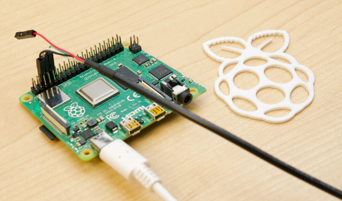
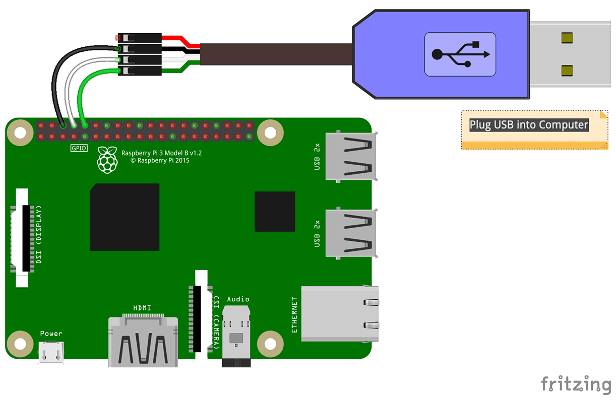
Plug the USB to serial adapter into the pins as pictured below on the Pi (Black to GND, White to GPIO 14/pin 8 (UART TX), and Green to GPIO 15/pin 10 (UART RX)):
Open a terminal window on your Mac, and run
ls /dev | grep usb- Note the
tty.usbserial-andcu.usbserial-numbers in there. That's the device you'll connect to on your Mac.
There are a number of ways to interact with the serial console on a Mac (and most are the same as on Linux, with sometimes minor usage differences), but the two I've used in the past are minicom and screen.
Use CoolTerm
Sometimes if I'm doing a lot of debugging, I like to use a good serial terminal GUI, and my favorite is CoolTerm. It has a quasi-intuitive GUI interface for any kind of serial terminal viewing.
In its options, select the /dev/tty.usbserial-0001 device, and then click 'Connect'.
Use minicom
- Install minicom (
brew install minicom) so you can emulate a terminal connected over serial. - Run
minicom -b 115200 -D /dev/tty.usbserial-0001 - Boot the Pi.
- Within a few seconds, you should see data in your session.
Note: In minicom, the Meta key is mapped to 'Esc' by default, at least on macOS. So press 'Esc-Z' to get help. Additionally, if you're attaching to a device using minicom running on the Pi, you have to press Enter, then Ctrl-A, then Q, and Enter again to exit minicom. Fun!
Use screen
- Run
screen /dev/tty.usbserial-0001 115200 - Boot the Pi.
- Within a few seconds, you should see data in your session.
Note: To exit the screen session, press Ctrl-A, then Ctrl-K, and confirm you want to exit.
See also: Adafruit's guide to using a serial console on the Pi.
I've done this process a few times in the past, but I've grown tired of looking back at old notes to remember specifically which pins to use on the GPIO, since I don't do it that often and the pins are unlabeled on most Pis. Hope this helped!
Update: I also forgot to mention—it's possible to get output from the Pi's own bootloader (at an even earlier stage) using the
BOOT_UARToption supplied to a custom EEPROM build; see cleverca22's post in the Pi Forums for details.
Comments
You can use another Pi to access the other by crossing rx/tx between the three wires. I find it pretty simple and reliable - enough that I dont remember where my usb-ftdi adapters are anymore.
True! I often don't have a spare monitor around though with all the Pis I'm running, so using USB to UART is easier since I almost always have my laptop on hand.
Right. But maybe you don't have a USB serial adapter handy, but do have a spare (second) Raspberry Pi. You can run the second Raspberry Pi headless, say, a Zero W. The goal is to ssh from laptop to this second Pi then use it's serial connection. The second Pi will need USB power, which for a Zero you should be able to get from your laptop. To allow a network connection from your laptop to the second Pi, you have a few choices:
1. Add USB network adapter to the second Pi and use an Ethernet cable
2. Configure the second Pi as a Wi-Fi access point you can connect to with your laptop
3. But for me the real winner is to set a Pi Zero up as a USB Gadget
3a. Set up the Pi Zero as an Ethernet Gadget (laptop will see Zero as USB Ethernet device when connected)
3b. Even simpler, set up the Pi Zero as a Serial Gadget (doesn't require a Zero W, a plain old Zero will work)
With an Ethernet connection, ssh to the second Pi and run minicom in the session. To connect to a Serial Gadget, instead run minicom on the laptop to connect to the second Pi, then run minicom to connect to the actual target (and be reminded of "Inception").
If you use a Zero W with no headers you can solder three wires to it with a triple header socket on the other end. (Don't forget to cross RX/TX as abeck mentions.) This is small enough to easily fit in a bag's pocket for easy traveling.
Cons (vs USB serial adapter):
* This is more complicated (but a great learning opportunity)
Pros (vs USB serial adapter):
* You may already have a Pi Zero laying around.
* A Pi Zero can be configured to do a lot more than just act as a serial bridge. (It's a great addition to your Go Bag.)
You can just ssh into the second one and run screen there.
True...
screenception.Thank you so much. I had an urgent need to check the UART output from a raspi 3 and I didn't have USB to TTL UART cable and no easy way of getting one within 2 weeks. I was sure connecting GPIO pins on two raspis should be possible but all Internet articles assume I have one of these specialised cables. The additional change I had to make was set `dtparam=uart0=on` in /boot/firmware/config.txt on my raspi 5 and then I could connect with `screen /dev/ttyAMA0 115200` from my spare raspi 5.
I quite like booterm program for accessing serial devices. it supports listing connected serial devices and by default connects to the newest serial device in the system
https://github.com/wtarreau/bootterm
Will this also work with Windows, using a terminal program?
Yes. You'll need a serial terminal app. Putty is a popular option.
I am having a broken rpi4 where it also just has a study green light, but nothing seems to be in the TTY. Any ideas what I might be doing wrong?
"Nothing seems to be in the TTY."'
# in the boot directory config.txt file
# Disable pull downs
gpio=14,15=np
enable_uart=1
check if your buffer level voltage is 3.3V (DO NOT exceed 3.3V and drive with straight 5Volt TTL)
USE a logic probe or oscilloscope probe to view signals on Raspberry Pi 4B pin 8 (TXD) , pin 10 (RXD)
check your wiring hookup? Did you connect RXD to a RXD, or TXD to a TXD? They need to be swapped TXD out to RXD in.
Connect and enable a separate GPIO pin to the pin 8 (TXD) and watch for changes on signal level? (use if don't have logic probe available )
enable a different UART part with different pins, enable that UART in the config.txt file. Write a program to print a single character every second, as a test.
Hey Jeff,
This saved my bacon. My PIHole's IP address was set and I could not SSH into it so Serial to the rescue. Updated network configuration and PiHole is back in business. Thank you for posting this Jeff!
Del Mar
Jeff, I can connect my pi0 over a usb/serial cable to a pi4 or pi5, and use screen from the bigger pi just fine. But I can't get it to work from my MacBook Air M2. When I do "ls /dev | grep usb", I get nothing at all. Looking further at /dev, there's nothing like what you show. Got any hints for me? (and, is it correct to do that initial bit with the red wire disconnected, as you show in the diagram?)
Actually, whether I power the pi from the serial cable to a v5 pin, or from a power supply, nothing shows up on the Mac.