As a kid, I never had a Game Boy, Game Gear, or any other handheld console. Heck, as luck would have it I've never owned a Nintendo Switch, either.
I've played console and PC games, I've only used handhelds twice: once in middle school, when a friend let me borrow his Game Gear for a day, and last year year when my dad brought over his Nintendo Switch—which my kids quickly commandeered.
I guess out of a sense of jealousy, I decided the first thing I should do with Raspberry Pi's latest hardware, the Pi Zero 2 (see my review here), is build myself a handheld retro gaming console.
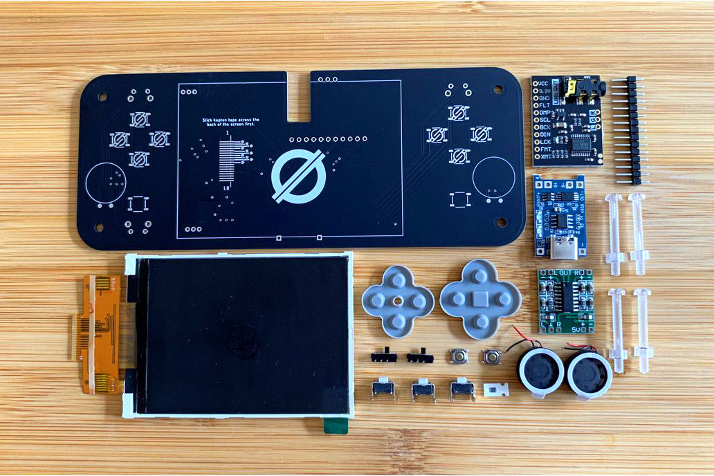
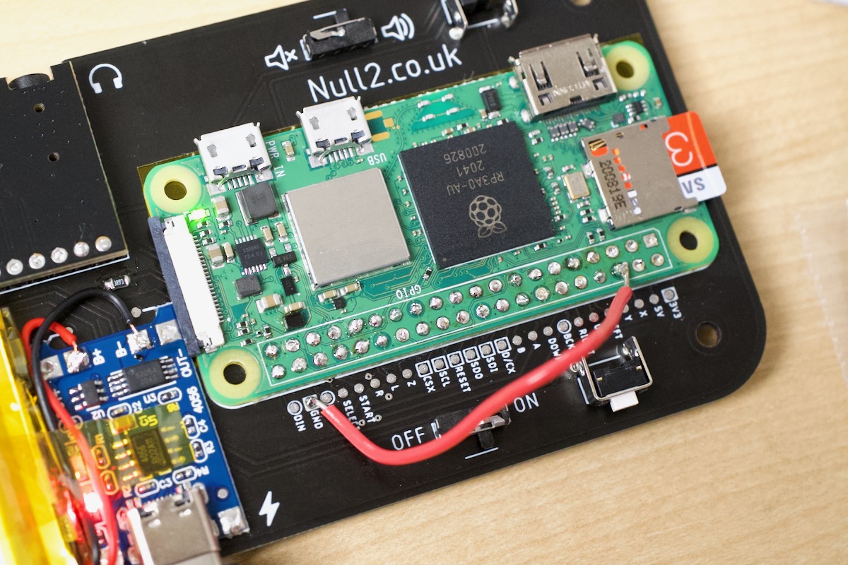
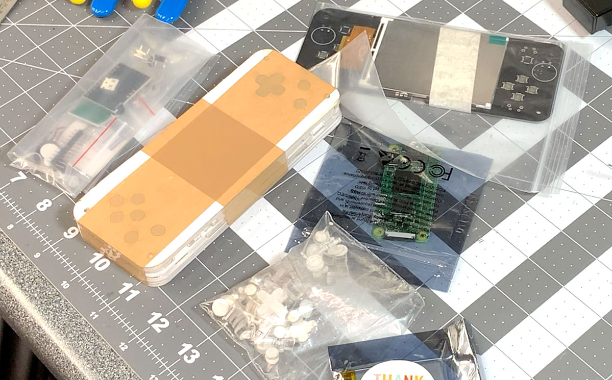
And what better way than with the Null 2 kit (pictured above, from it's Tindie page), a kit integrating off-the-shelf components on a custom PCB, wrapped up nicely in a custom acrylic case.
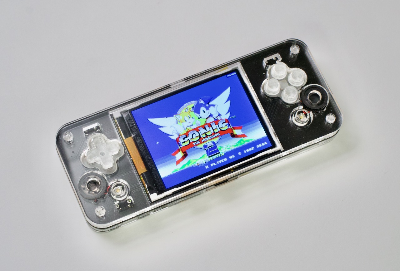
I finally have my own portable gaming handheld—and even better, I hand-made it! I even 'hand-made' some of the software, too, since the official Null 2 image—at least at the time of this writing—doesn't work on the Pi Zero 2 hardware!
Video
I have a video of the build process on my YouTube channel, for those who are more visual learners:
Hardware
After completing the build, I don't know if I'd recommend the Null 2 to someone completely new to soldering. Or maybe I would. Through the course of putting this thing together, I got to practice:
- Through-hole soldering
- SMD soldering
- SMD flat/ribbon cable soldering
- Desoldering (for a few oopsies)
And here is a picture of my workbench as I dove into the soldering:
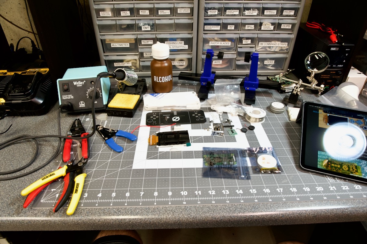
Let's list all the tools I used (Amazon affiliate links):
- Weller WES51 Soldering Station
- Menda Alcohol container (not my favorite, but it holds 91% isopropyl alcohol for cleaning things)
- WS-5 Adjustable stripper (so nice for tiny wire stripping)
- Dowell Micro cutter (for snipping leads close to the board)
- Hakko long-nose pliers
- Hakko CHP 7-SA Tweezers (There's no way I can work with tiny SMD components without these)
- APT 1mm 1" Kapton heat-resistant tape (Used in many steps)
- AUSTOR Desoldering wick and solder sucker (I'm good at making mistakes, so these help me fix them)
I also ended up using flux, solder, and some Q-tips to clean some parts with alcohol once I splashed flux all over them :)
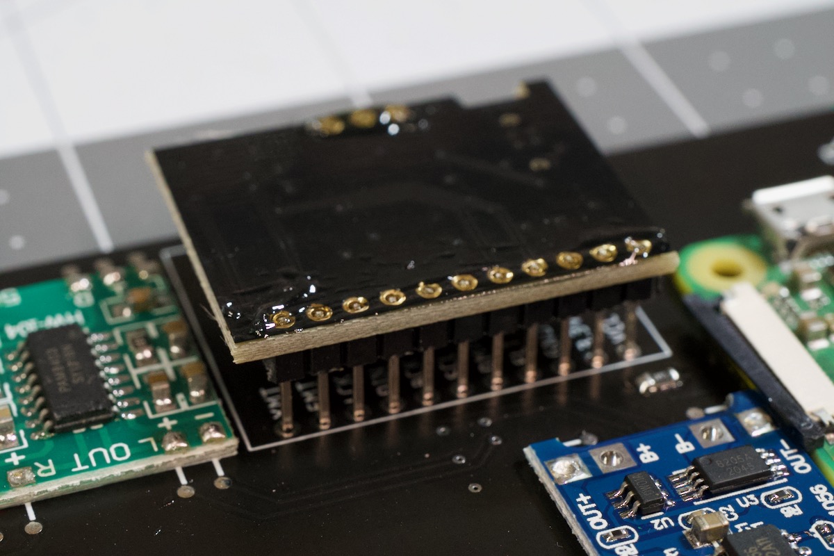
The most nerve-wracking part was soldering the Pi Zero 2 to the Null 2. The first step is taping it to the board so it aligns with the pads on the board:
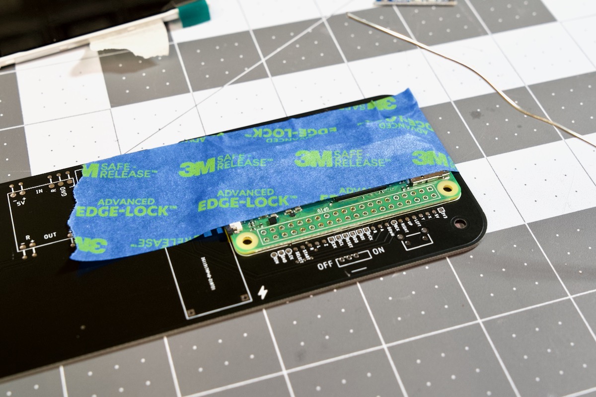
It's a weird soldering method. I guess you could call it "blind cup-hole soldering". You basically 'fill in' the through-hole on the Pi's GPIO pins, and hope that the solder makes a connection with the surface pad under the through-hole.
In a sick twist of fate, every single GPIO tested out fine except for the GND pin the Null 2 uses. So, I had to bodge a separate GND connection to one of the other ground pins on the Zero 2.
In the end, I'm not proud of it, but this was the first time I'd done the 'through-hole cup' method of soldering, so 39/40 connections seems like a pretty good average! I later switched out that red jumper wire for a thin bit of enameled copper wire, so it would fit in the case better.
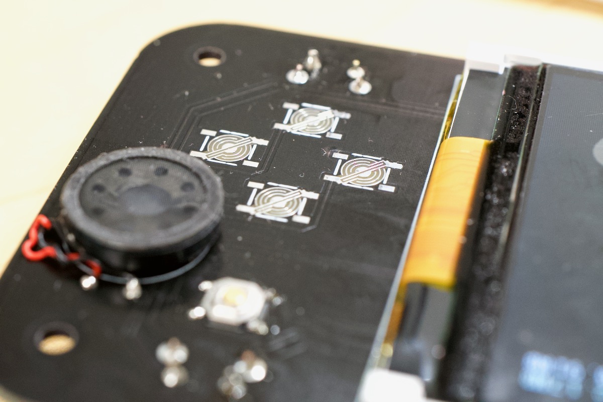
After that snafu, things went well, though soldering a few of the SMD components (like the resistor pictured below) can be annoying. Luckily there are only a few surface-mount buttons, a resistor, and the screen that have to be done this way.
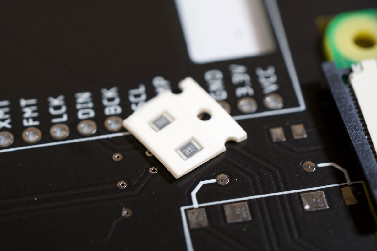
The key is to put some flux on the joint, solder it, then if you overloaded it, grab a spool of solder wick and pull off some of the excess solder. Rinse and repeat.
Flux is your friend.
Anyways, I got the battery mounted, I charged up the battery via USB-C, and then I powered on the board... and nothing happened!
I thought I must've broken something, but after re-testing all the test points, it seemed the hardware was wired correctly. Eventually, I found that the problem was the official Null 2 Pi image (at least at the time of this writing) didn't include device tree files (.dtb's) for the Pi Zero 2.
Switching to the official Pi OS image got the Pi to boot, but that made a new problem...
Software
Building RetroPie on the Pi OS image is not quite 'simple', and takes a very long time—hours and hours. And, as I found out after trying for a couple days, it doesn't currently build on 64-bit Pi OS, and I had trouble getting it to build on the 32-bit version on the Zero 2 as well...
So to make things easier, I decided to try customizing the RetroPie OS image to get RetroPie booting and all the hardware (screen, buttons, and audio) working.
The Null 2 site has a downloadable set of instructions for 'making your own' image. Unfortunately, those instructions seem to be a bit out of date with the latest version of Linux, so I'll outline every step in detail.
Getting RetroPie
Since the Pre-made RetroPie Raspberry Pi images already have a Pi 3 version, and the Pi 3 shares the same processor as the Pi Zero 2, that image should work after you flash it to a microSD card...
But I discovered the WiFi chip in the Zero 2 is actually slightly different than the one in the Zero W and 3 B+ the current RetroPie image (as of Nov 2021) is compatible with. Because of that, a newer kernel is required so it will load the correct brcmfmac43436 driver for the Zero 2. So until an official release newer than 4.7.1 is available, you have to download the RetroPie weekly build if you want working WiFi and Bluetooth.
When you flash the image to your microSD card, you need to set it up for headless remote access, because the Null 2 doesn't allow use of the USB or HDMI display ports.
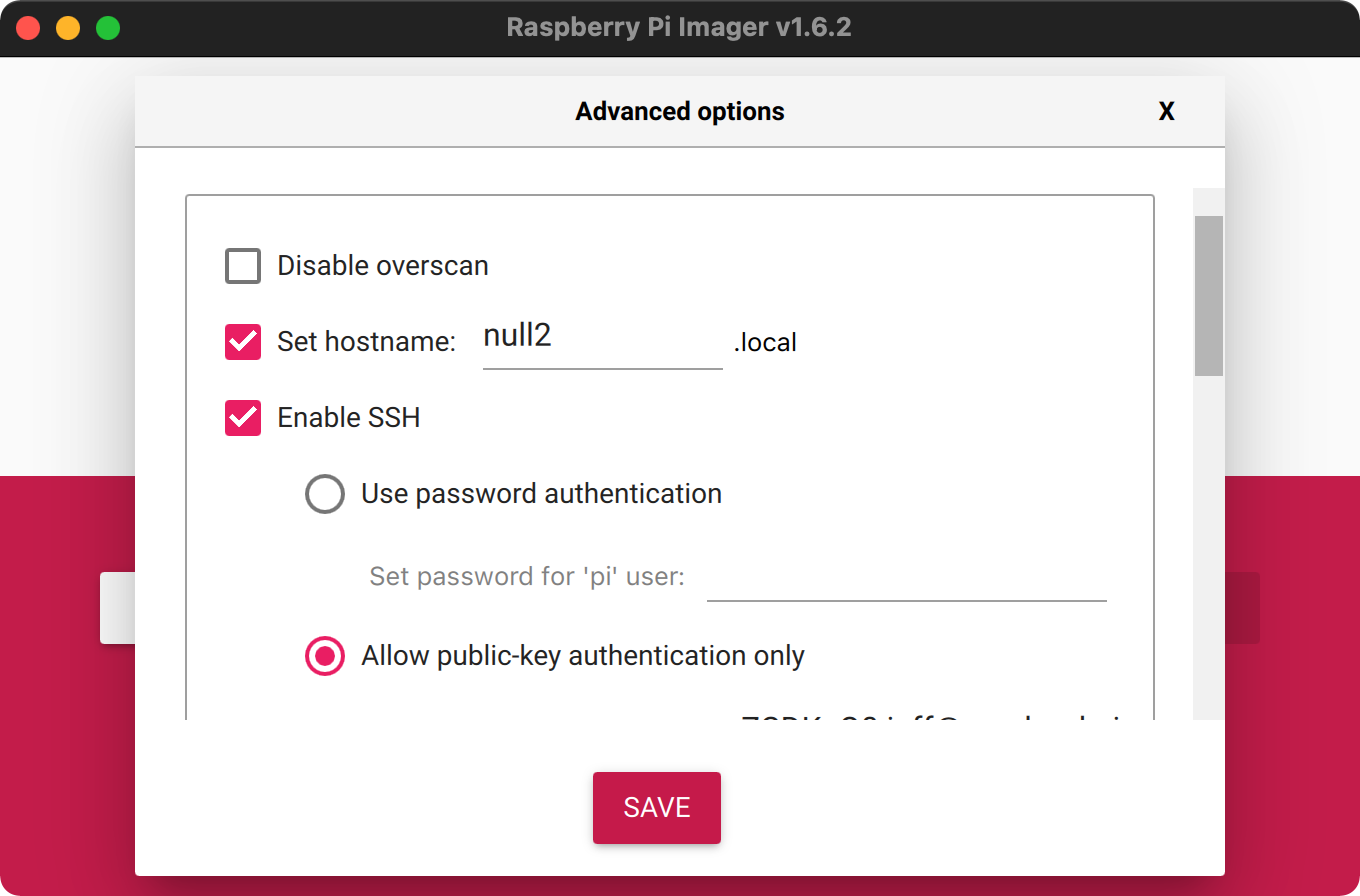
Using the Raspberry Pi Imager, you can edit the RetroPie OS configuration before you write the image to your card by pressing Shift-Ctrl-X. In those options, make sure you either set an SSH password or paste in your public SSH key so you can log in. You should also set up WiFi credentials here too.
I set the hostname to null2 so I could access the Pi at null2.local on my network (and not have to try to figure out its IP address on my own).
Save those settings, and write the RetroPie image to your microSD card.
After that's done, pop the card in the Pi Zero 2, and boot it up—it will likely take a couple minutes on first boot, as the Pi has to go through expanding the filesystem, and RetroPie does things like generating a new SSH host key.
After it's booted up, you should be able to headlessly SSH into the Pi using ssh [email protected] (assuming that's the hostname you picked).
Note: If you can't get connected, it could be WiFi isn't enabled correctly on the RetroPie image. The easiest solution is to grab a second Pi Zero 2 or 3 B+, pop the microSD card in it, plug that Pi into a display, keyboard and mouse, and configure WiFi there, then stick the microSD card back in the Null's Pi.
Now it's time to start bringing up all the hardware on the Null 2. First, the display:
Getting the ILI9341 SPI display working
Since the fbtft_device module is no longer in the Linux kernel, I had to instead use the juj/fbcp-ili9341 driver for the display. This driver allows the little 240x320 display to be driven at 60Hz over SPI, which is no small feat!
But getting it compiled on the Pi was a little bit of work, since I had to translate some of the Null's pin assignments into the compilation command. Here's what I did on the Pi itself over SSH to get the screen working initially:
cd ~
sudo apt-get install cmake
git clone https://github.com/juj/fbcp-ili9341.git
cd fbcp-ili9341
mkdir build
cd build
cmake -DILI9341=ON -DGPIO_TFT_DATA_CONTROL=24 -DGPIO_TFT_RESET_PIN=25 -DSPI_BUS_CLOCK_DIVISOR=6 -DSTATISTICS=number ..
make -j
sudo ./fbcp-ili9341
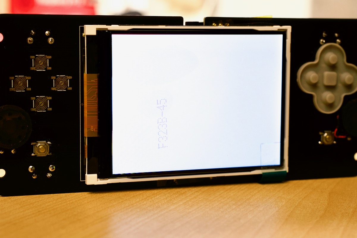
At the end of that process, the driver should start rendering the Pi's display to the screen, and you should see something like this:
Press Ctrl-C to stop the display from rendering. It's a little blurry since the HDMI resolution doesn't match the SPI display, so we can fix that by editing the /boot/config.txt file (sudo nano /boot/config.txt) and adding the following HDMI settings near the top:
hdmi_group=2
hdmi_mode=87
hdmi_cvt=320 240 60 1 0 0 0
hdmi_force_hotplug=1
Next, I needed to make it so the screen would turn on at boot. So following the driver's README, I edited /etc/rc.local with sudo nano /etc/rc.local, and added the following line before the final exit 0 line:
# Enable ILI9341 display driver.
sudo /home/pi/fbcp-ili9341/build/fbcp-ili9341 &
Then I rebooted the Pi to make sure the screen would come up. And it did, yay! Except, now I realized it was upside-down. I edited the boot configuration with sudo nano /boot/config.txt and added the following line alongside the HDMI configuration to rotate the display:
display_rotate=2
After a reboot, the display was rendering right-side-up.
Note: Due to the way the SPI display connection works, you could experience 'tearing' or other artifacts depending on the Pi model you're using, overclock, and other settings. See the README in the display driver's repo for a lot more detail about how to solve these issues if you have them.
Buttons for retrogame
As suggested in the Null 2 guide, I used Adafruit's Retro Gaming Guide to add software key control using retrogame:
mkdir ~/Scripts && cd ~/Scripts
curl https://raw.githubusercontent.com/adafruit/Raspberry-Pi-Installer-Scripts/master/retrogame.sh >retrogame.sh
sudo bash retrogame.sh
When prompted, choose option 1 (we'll override it later), and press enter.
Reboot when prompted, and once rebooted, edit the retrogame config file with sudo nano /boot/retrogame.cfg, and place the contents of the boot/retrogame.cfg file that comes bundled with the other Null 2 custom image resources. Here are the relevant bits from that file:
LEFT      04  # Joypad left
RIGHT     17  # Joypad right
UP        15  # Joypad up
DOWN      27  # Joypad down
LEFTCTRL  22  # 'A' button
LEFTALT   23  # 'B' button
Z         02  # 'X' button
ENTER     13  # 'Start' button
SPACE     16  # 'Select' button
X         03  # 'Y' button
A         06  # 'L' button
S         12  # 'R' button
Y         05  # Exit button
Reboot the Pi after saving that file, and the key assignments should now be working. The fastest way to test is to press the system button (the bottom left button on the underside of the board) and see if it prints a 'Y' character in the search box. If it does, the button assignments are working—nice job!
System control buttons (shutdown and volume control)
The Null 2 custom image guide docs includes a systembuttons.py script. I had to modify it a little to work with Python 3, so here's the latest version of that file:
You need to paste the contents of that gist into /home/pi/Scripts/systembuttons.py:
mkdir ~/Scripts
nano ~/Scripts/systembuttons.py
# Paste contents into file
I also noticed the script uses the keyboard Python library, which isn't in the default Pi OS install. So I added it with:
sudo apt update
sudo apt install -y python3-pip
sudo pip3 install keyboard
Then I edited /etc/rc.local with sudo nano /etc/rc.local, and added the following line before the final exit 0 line:
# Enable Null 2 system control buttons.
sudo python3 /home/pi/Scripts/systembuttons.py &
To test them, I rebooted, then pressed the system button (the push button along the bottom left rear of the board) and 'B' (the bottom button on the right directional pad). And the system shut down, yay!
Audio setup for the PCM5102a
The Null 2 uses a fairly common PCM5102a audio board, and HiFi-Berry supports it natively. All you have to do is edit the boot config file with sudo nano /boot/config.txt and make the following changes:
# Make sure this line is commented out (put a '#' in front) if it is not already.
#dtparam=audio=on

# Add this line at the bottom of the file.
dtoverlay=hifiberry-dac
Then reboot, and check if the sound card is listed when you run the command aplay -l:
pi@null2:~ $ aplay -l
**** List of PLAYBACK Hardware Devices ****
card 0: sndrpihifiberry [snd_rpi_hifiberry_dac], device 0: HifiBerry DAC HiFi pcm5102a-hifi-0 [HifiBerry DAC HiFi pcm5102a-hifi-0]
  Subdevices: 1/1
  Subdevice #0: subdevice #0
To make this the default audio playback device and enable volume control, run sudo nano /etc/asound.conf and paste in the following configuration:
pcm.!default  {
 type plug
 slave.pcm "speakerphat"
}

ctl.!default {
 type hw card 0
}

pcm.speakerphat {
  type softvol
  slave.pcm "plughw:0"
  control.name "Master"
  control.card 0
}
Note: The original Null 2 image running on an older version of Pi OS and ALSA was able to use hardware-based volume control with a simpler configuration. But after a few hours' research, I found that newer versions require the use of
softvolas I have configured above, since the PCM5102A DAC the Null 2 includes is an older variety that is not supported for direct hardware volume control anymore.
Reboot again, and you can test playing a WAV file, like so:
aplay /usr/share/sounds/alsa/Front_Center.wav
Assuming you don't have the Null 2's mute switch muted, you should hear a voice say "Front... Center". And it might be a little loud. Should've warned you!
To turn down the volume, you should be able to press 'System' and 'left bumper' on the edge buttons on the Null 2. To turn up the volume, you should press 'System' and 'right bumper'.
Note: If the volume controls aren't working, it could be the command in the
systembuttons.pyscript are not correct for your board. Runamixerand see what the name of theSimple mixer controlis. If it's notMaster, you need to change that value in the script to whatever the name is on your board.
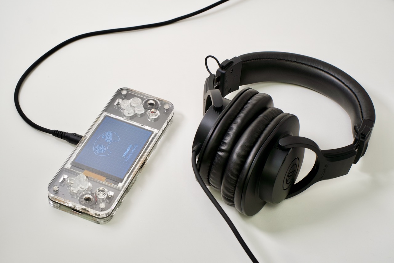
The headphone amp should also be working—to use it, just plug in some headphones. The speakers don't automatically switch off though, so you have to manually mute them if you want to have sound just coming through the headphones.
RetroPie Settings
Before getting fully invested in any of the old games I wanted to play, I decided to spend a few minutes customizing the RetroPie setup to my liking.
First, I went into 'ES Themes' in the RetroPie Configuration screen, and installed the anthonycaccese/tft theme. Then I pressed Start, then changed to the "TFT" theme in UI Settings > Theme Set.
On my aging eyes, this theme was a lot more legible than the default Carbon theme.
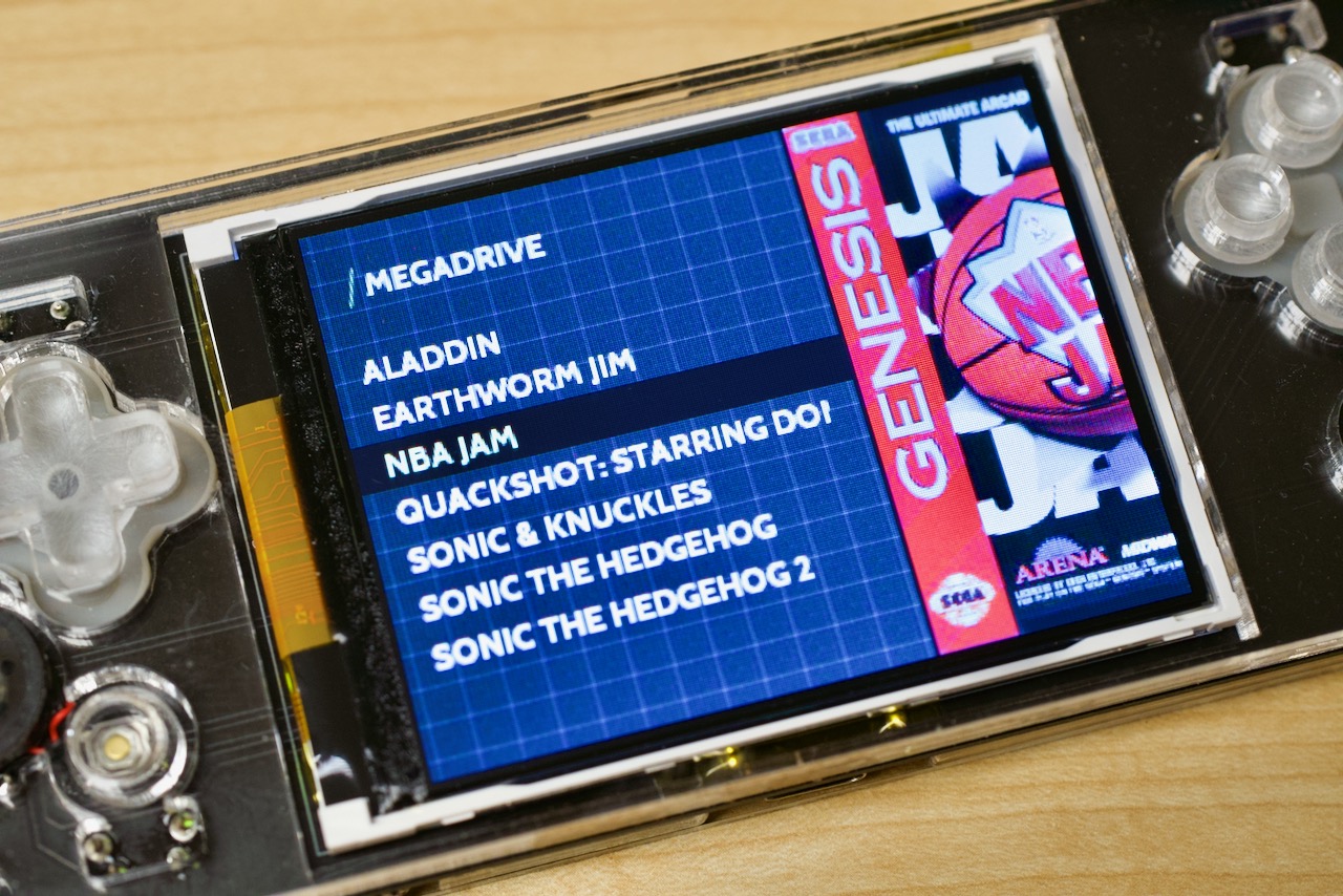
Second, I wanted cover art when browsing games, so I visited the 'Scraper' in the Main Menu (press Start to access), and chose to 'Scrape Now'. It makes browsing your games list a lot prettier:
Third and finally, I wanted to see how many FPS I was getting playing various games—I know in the past the Pi Zero was lampooned as a serious retro gaming machine, because it would stutter even on lowly NES titles.
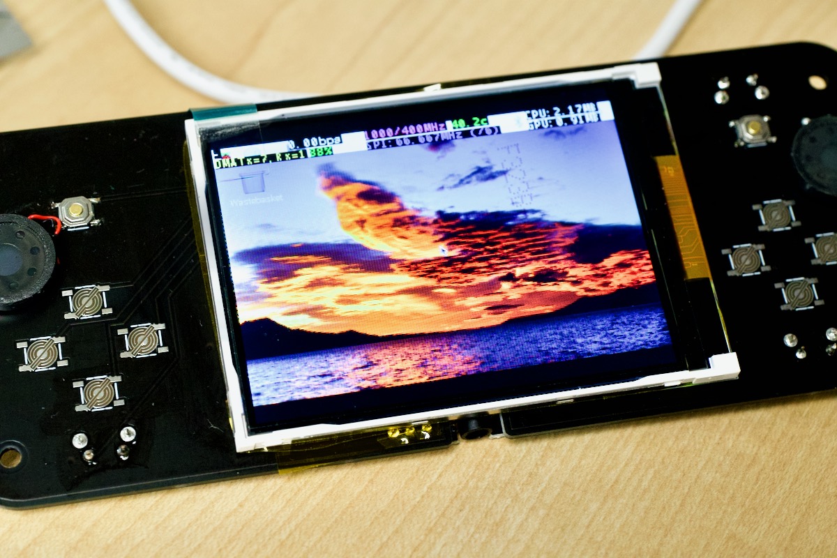
FPS display is a RetroArch option, so to enable it I went to RetroPie configuration menu, then chose 'RetroArch'. Inside RetroArch's menu, I went to Settings > On-Screen Display > On-Screen Notifications > Notification Visibility > Display Framerate, and chose 'ON'. To make the change persist, I went back out to Configuration File > Save Current Configuration.
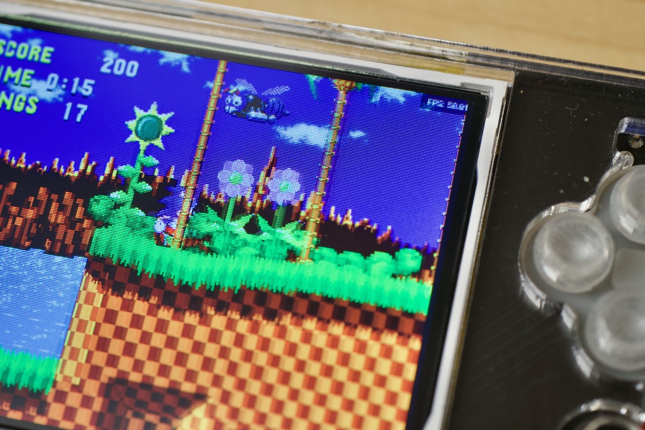
Seeing 58-59 FPS in even more complex NES and Genesis/Megadrive games makes me pretty confident in saying the Null 2 is a lot more fun at 60 Hz with the Pi Zero 2!
I'll talk more about performance in my review on YouTube, but the Zero 2 seems to be able to play most NES, SNES, GBA, PS1, Genesis/Megadrive, and even a few N64 games without much issue.
Making it Fancy
I decided to pay to have acrylic laser cut to the Null 2 specifications. You can either choose one of the suppliers recommended by Ampersand (I went with RazorLAB), or download the files and make the cuts yourself (if you have access to a laser cutter and acrylic sheet stock).
But there's also a set of STL files for a 3D printed Null 2 case, which can be had a little more cheaply (though it doesn't end up looking quite as nice).
If you go with acrylic, the two parts that could be daunting (and require extra gear) are 'welding' a few of the parts together permanently, and sanding down the buttons so they fit correctly.
For the welding, I bought Weldon #4 with an Applicator Bottle, and my best advice is to treat the thing like danger-water. Make sure you're in a well-ventilated room, have something underneath to absorb any excess that drips out (I found it makes a great paint remover... oops!), and try to 'squirt in' a little extra under each part—it kinda magically spreads itself everywhere, and if you don't put enough under the part you're gluing together, there will be little bubbles.
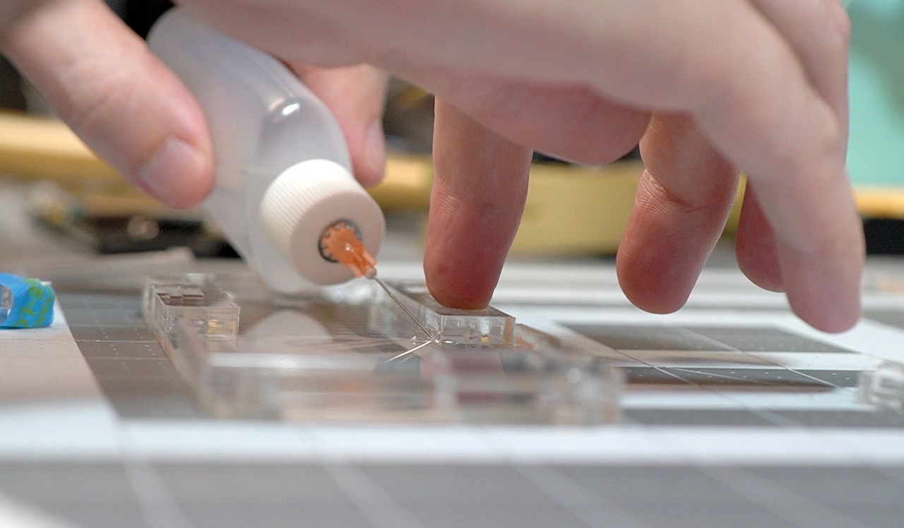
Also, align everything perfectly because you get one shot at this process.
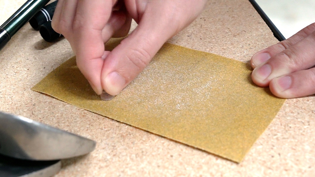
The sanding was a little annoying, just because there was a lot of material to remove to get the buttons to fit correctly with the rubber pads underneath. I set down a piece of 120 grit sandpaper and just went at it with each of the buttons and the D-pad acrylic until they were thin enough to fit:
Odds and Ends
A few random notes about RetroPie:
- The FPS counter is tiny on the 320x240 display, and I haven't figured out a way to make it larger.
- If you go into the retroarch in-game menu, you can take screenshots or even make recordings, but the latter can really affect in-game performance. If you do this, the files are stored in a directory under
/home/pi/.config/retroarch.
A few things I'm still working on:
- Bright parts of the display flicker during heavy processing when the battery is less than 50%. It would be nice if there were a way to get rid of that flicker.
- Overclocking works, but the case doesn't dump heat that well, so you start getting throttled after a few minutes of gameplay. I think it's best to stick at the 1 GHz clock on the stock Null 2 build. A heatsink cutout on the back may help.
- I tried getting everything working on 64-bit Pi OS, but ran into two issues: first, RetroPie's source install process had a number of errors I couldn't figure out. And second, the display driver might or might not work there—yet.
- The
display_rotate=2option rotates HDMI and SPI display output; you can actually make it so only the SPI output is rotated if you change one of the driver options when you compile it.
A few things I didn't particularly like about the Null 2:
- Sanding the buttons was a bit annoying.
- Having an analog volume knob for the built-in speakers would be nice. The hotkey method is a bit annoying and was hard to get right in software.
- There's no backlight control, so it's a bit annoying trying to use it at night.
- There's a vague warning about not using the device while plugged in and charging, though researching the TP4056 charging board, I found mixed results as to whether it would protect against overcurrent to the battery if plugged in and using the device after the battery was fully charged; so I guess I'll go along with that and recommend not using it while plugged in.
Conclusion
You know how they say it's the journey, not the destination? I think that's what I've learned over the course of getting everything working on the Null 2 with the Pi Zero 2 W.
It doesn't help that I was trying to get brand new (and unreleased) hardware working on a board that was originally built for the older Pi Zero! And sometimes, trying to find the right help or ask questions was difficult too, because I couldn't just say "well, that doesn't work because this is a different board..."
But in the end, this was a fun project to build, and I love how compact and slick the thing looks on my desk. I've had my kids test it out and while I don't think it'd last too long in their young hands, the fact that every single part (maybe outside the hard-to-desolder Pi Zero) can be replaced with a cheap replacement component I could buy almost anywhere makes me happy inside.
I would recommend the Null 2 to anyone who really wants to take ownership over their 90s-era Retro gaming handheld build. If you want something mostly pre-made where you just slap in a Pi and start gaming, this is not the kit for you!
Right now the Null 2 is out of stock on Tindie, but supposedly Ampersand is working on another batch now. Hopefully everyone who wants one will be able to get a kit soon!
Make sure to subscribe to my YouTube channel so you don't miss my video on the Null 2 Pi 2 build!
Comments
Awesome write up. Mine should be arriving soon and I am probably going for a custom build in a NDS shell. No idea if i'll manage to drive two displays or not. This looks clean and simple. I wonder why they didn't have gpio type pins facing up on the PCB for easy alignment and soldering to the Pi. Would make more solid connections.
I have some ideas for open source Raspberry Pi projects, like a SIP phone. But, don't know who to go to for design since I do not have any electronic design experience at all. Do you know of where one can find a designer to assist with projects? I'd even be willing to pay.
Thanks for figuring this all out. I have now successfully desoldered my Pi Zero (not for the faint of heart) and soldered a Pi Zero 2 W, soldered bodge wires where I ripped off pads in the process and tested all connections. Next is the software.
Wow, nice! I figured there wouldn't be a clean way to desolder the board—but only a couple pads off seems like the best result you could expect!
My Null 2 kit is supposed to arrive this week. However, after setting the software side of things up on my Pi Zero, I'm wondering if there's a way to go for the slightly larger 3.5" screen that does 640x480. I'm sure with the original Pi Zero, that doubling the resolution probably caused slow game play, but with the Pi Zero 2, I'm thinking that it might make sense to get the resolution to something that's more like what was native for many of these games. Time will tell. I'll see what the kit looks like when I get it...
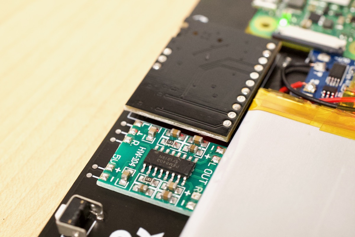
Also... Looking at the TP4506 module being used here... There are several different boards that use the TP4056 chip to do charging of Li-Ion batteries. The one you show here in pictures has multiple chips. That multi-chip modules have extra chips for power management to handle over-charge, under-charge, and over-current conditions. There are other modules that only have the TP4056 chip and are less likely to handle over-charging/over-current conditions as well. If the Null 2 kit continues to come with the board you show, then it's possible that our concerns about over-current and such are less valid. However, as you state, an over abundance of caution is always a good policy.
I'm interested in trying this out I just have a multi part question. First part how difficult would it be to add a standard USB into one side and an HDMI out on the other and with that what kind of hurdle would it be to have it switch the main video/audio out to that hdmi when connected. Is short could I easily turn this into a retro-pi "switch"?