If you haven't already, watch How I almost broke MrBeast's 1-100 video, which provides context for this blog post.
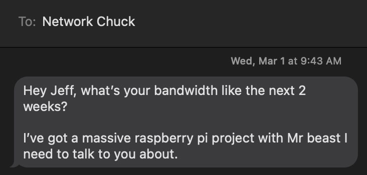
On March 1st, Network Chuck asked me if I had a couple weeks to help him build out a system to manage buttons and LEDs for a MrBeast video.
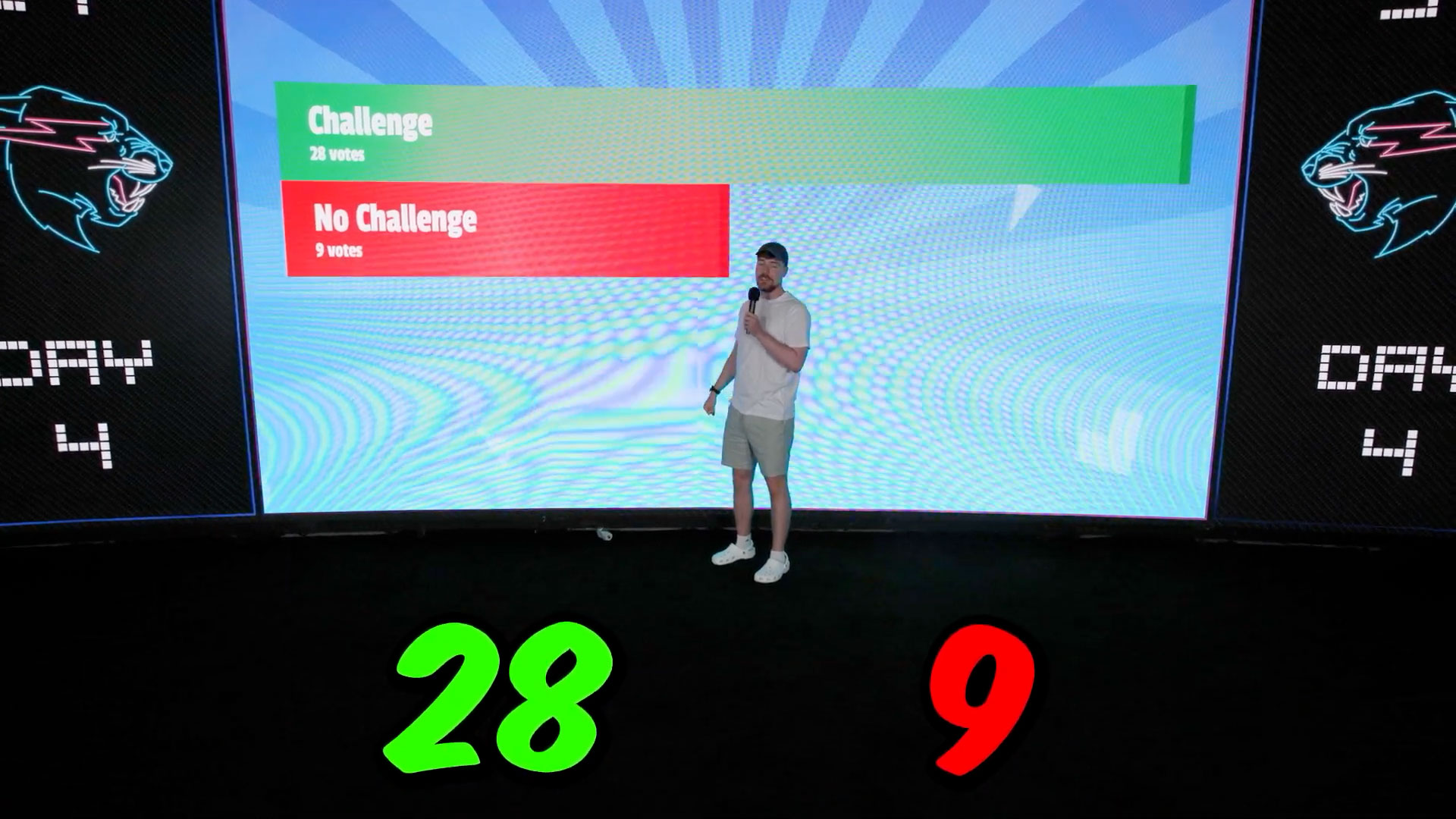
A few weeks later, we handed off our system to capable folks on the MrBeast team. In May, they published Ages 1 - 100 Fight For $500,000, and our handiwork was finally public—pictured is Jimmy Donaldson (MrBeast) demonstrating how contestants would vote:

This blog post explores our architecture decisions. Watch the companion video for more of the overall experience and challenges implementing the architecture.
Contents
- Requirements and Time Limitations
- Initial Design
- Choosing the right Hardware
- Building the Software (shell scripts, Python Flask, and SQLite)
- Managing Change
- What I'd do differently
Requirements and Time Limitations
We had less than 12 hours after first learning of the project to order 110 of everything required to build it.
The first few hours, we worked on gathering requirements.
Typically on an enterprise engagement I'd have days to weeks for this part, and it'd be handled by a sales team and solutions architect, with a few meetings with all the stakeholders before prototype code would be written and an MVP would be defined.
For this project we had 12 hours, and requirements were already pretty rigid (set construction was already starting). Less than 24 hours in, I had already written MVP code—we were flying through things at a fairly breakneck pace.
Communication was a challenge, as Chuck and I were having a couple meetings a day with those involved on the MrBeast side, and we were otherwise connected only via text messages. But we made do, and wound up with a decent understanding of what was needed.
Initial Design
We were working off the photo above, and were told we would be in charge of wiring up two buttons and some LED lighting in each room (there would be 100 of these rooms laid out in a football-field-sized studio).
That requirement was later expanded to three buttons (and for a time, three buttons with an LED individually controllable inside each one) and six strips of LED tape in each room. But for the initial equipment purchase, we had assumed two buttons and one or two strips of LED tape (oops).
At this point, armchair architects are saying to themselves (as I would be) "this project sure seems simple, not sure why they had any trouble at all!" I am reminded of the quote "you can already build such a system yourself quite trivially" regarding the launch of Dropbox in 2007 ;)
Hardware-wise, we needed to figure out the best buttons to use, and how to house them in a way that was as indestructible as possible (all ages—from toddlers to centenarians—would be using these things!). We also needed to figure out a way to wire the buttons and LEDs into whatever computer application we built that would aggregate the button press data, present it to the video producers in real-time, and allow them to control the room LED lighting as well (sometimes based on vote data, other times set as the producers wanted for a camera shot).
The MrBeast crew thought of putting a Raspberry Pi outside each room, wiring buttons and LEDs to it somehow. That 'somehow' was why I was called up :)
Choosing the right Hardware
Quickly, we had to determine the backbone of the system, and we had two basic options:
- Wire up all buttons and LEDs through to some central controller.
- Wire up a room's buttons and LEDs to a computer or microcontroller specific to that room, then network all those into a central controller.
You may scoff at the first option, but if the wiring was doable, a system with everything wired into one computer (with a bunch of breakouts to handle all the analog IO, or using CANBUS) would be easier to program, and introduce less risk on the software side.
But to avoid the wiring nightmare that would be required wiring up 100 rooms across the footprint of a football field, we went with the second option. Ethernet was also better understood by a larger number of people, and that pushed me even further towards its use (I would not be on set at all times, so using familiar tech is important!).
Now I was faced with a dilemma: whether to choose a microcontroller like an Arduino, ESP32, or Pico, or a full SBC (Single Board Computer) running Linux, like a Raspberry Pi. Whatever we chose, I would need to get 110 of them to North Carolina in less than 7 days, so availability was crucial.
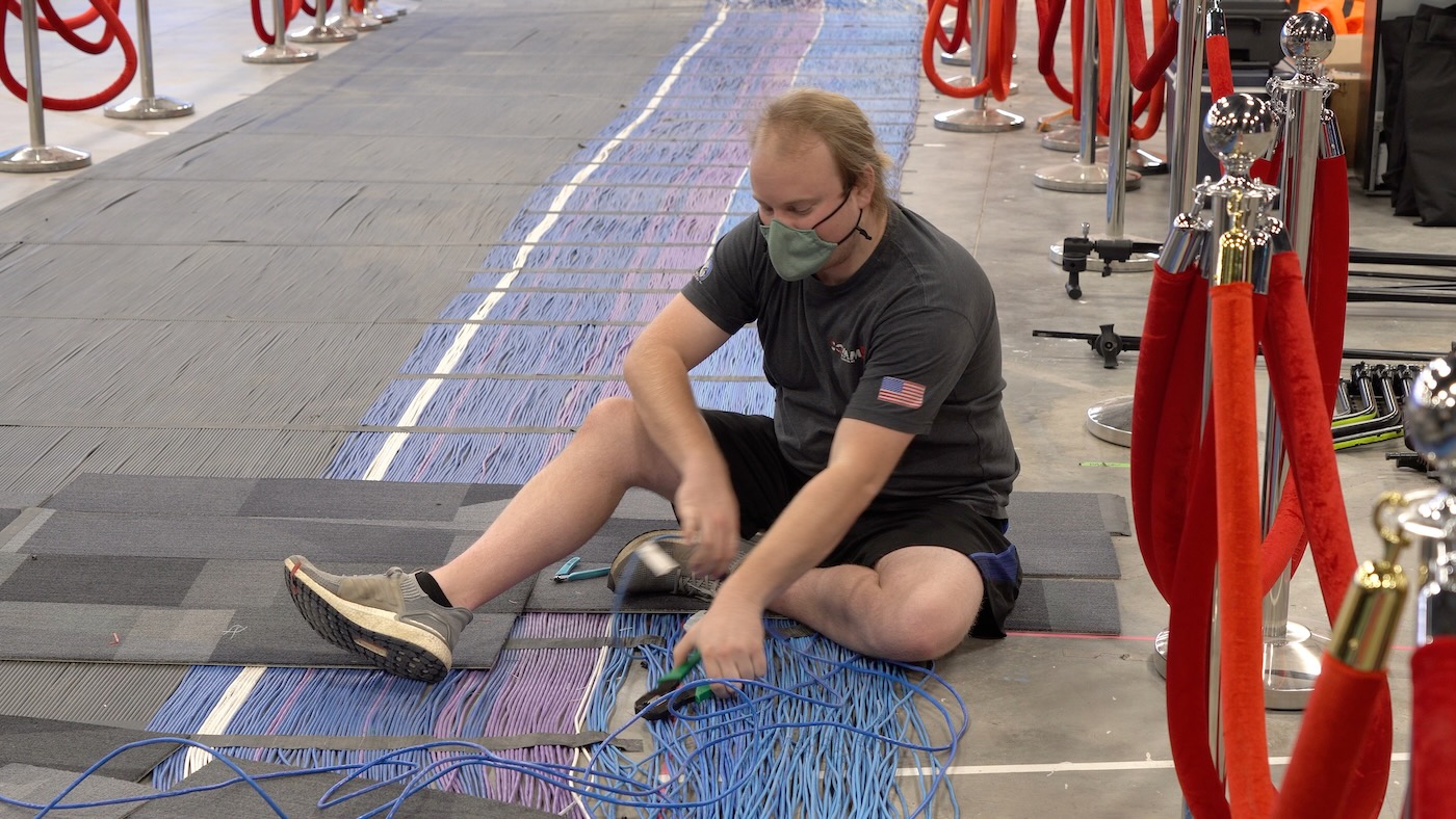
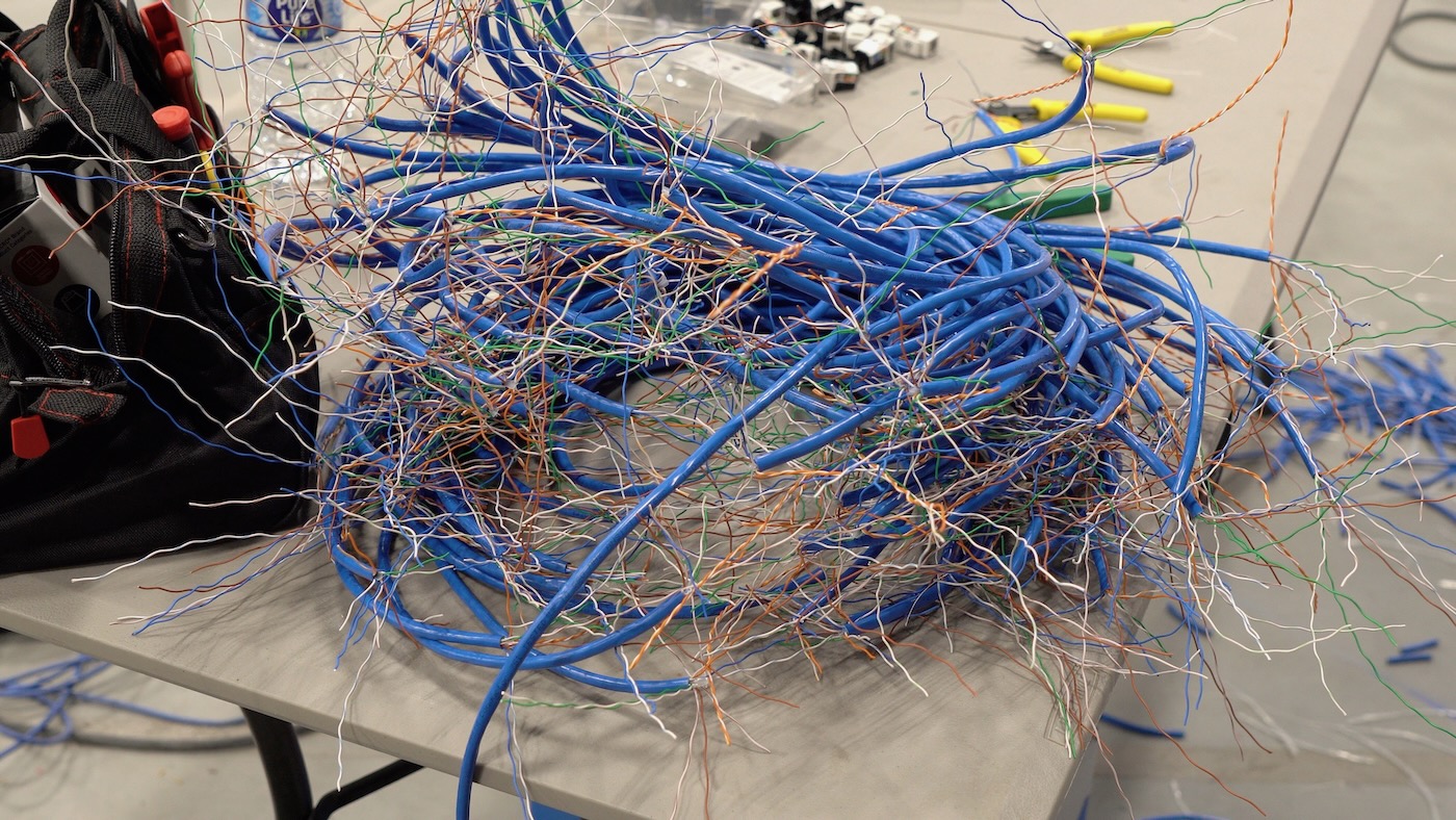
Above: Peitz digs through our home runs to find a network cable that was cut a bit short. And yes, that's a lot of cable. The black is all SDI (two GoPros per room), and the rest are Ethernet.
While WiFi might be adequate, I didn't want to rely on any wireless protocols, so wired Ethernet was chosen for the control plane's connection to all the rooms 1.
Unfortunately, Ethernet-enabled microcontroller designs that are available for immediate purchase, in bulk are few and far between, and many of the accessories that add Ethernet to existing dev boards are prohibitively expensive (compared to just buying an SBC) and would require extra setup time per room—that was another thing we were trying to minimize. Doing something 10 times is tough. Doing something 100 times... we wanted to minimize that.
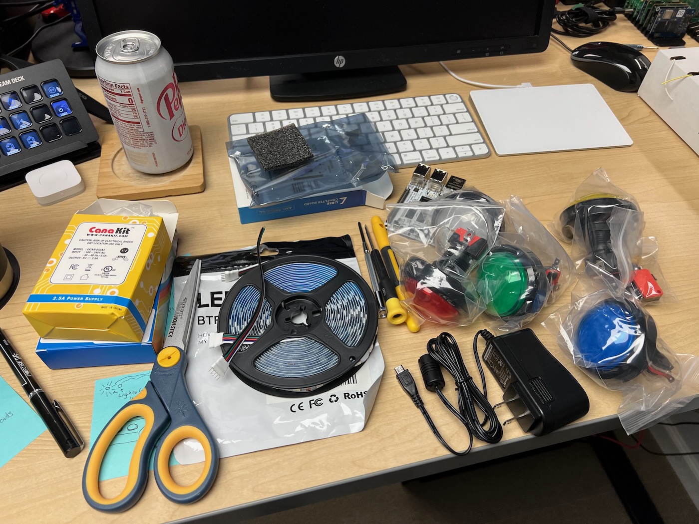
After a lot of deliberation, we settled on the parts laid out above (though the arcade buttons were swapped out for more aesthetically-pleasing flat buttons from Adafruit.
Libre Computing's Le Potato
Because we couldn't acquire 100 Raspberry Pis during the height of the Pi shortage, 2 we had to look elsewhere for an SBC.
We didn't need anything powerful—we only needed something on par with a Pi 2 or Pi 3, really, and our budget was less than $50 per room. Eventually, we settled on the Libre Computer AML-S905X-CC, a.k.a. Le Potato.
The board has been around for years—long enough to refine some of it's rough edges—and I thought it would offer the least amount of resistance when it came to the GPIO interfaces. Critically, it was the same form factor as a Pi 3 (with the same GPIO pinout), so the relay HATs we bought would fit and should work.
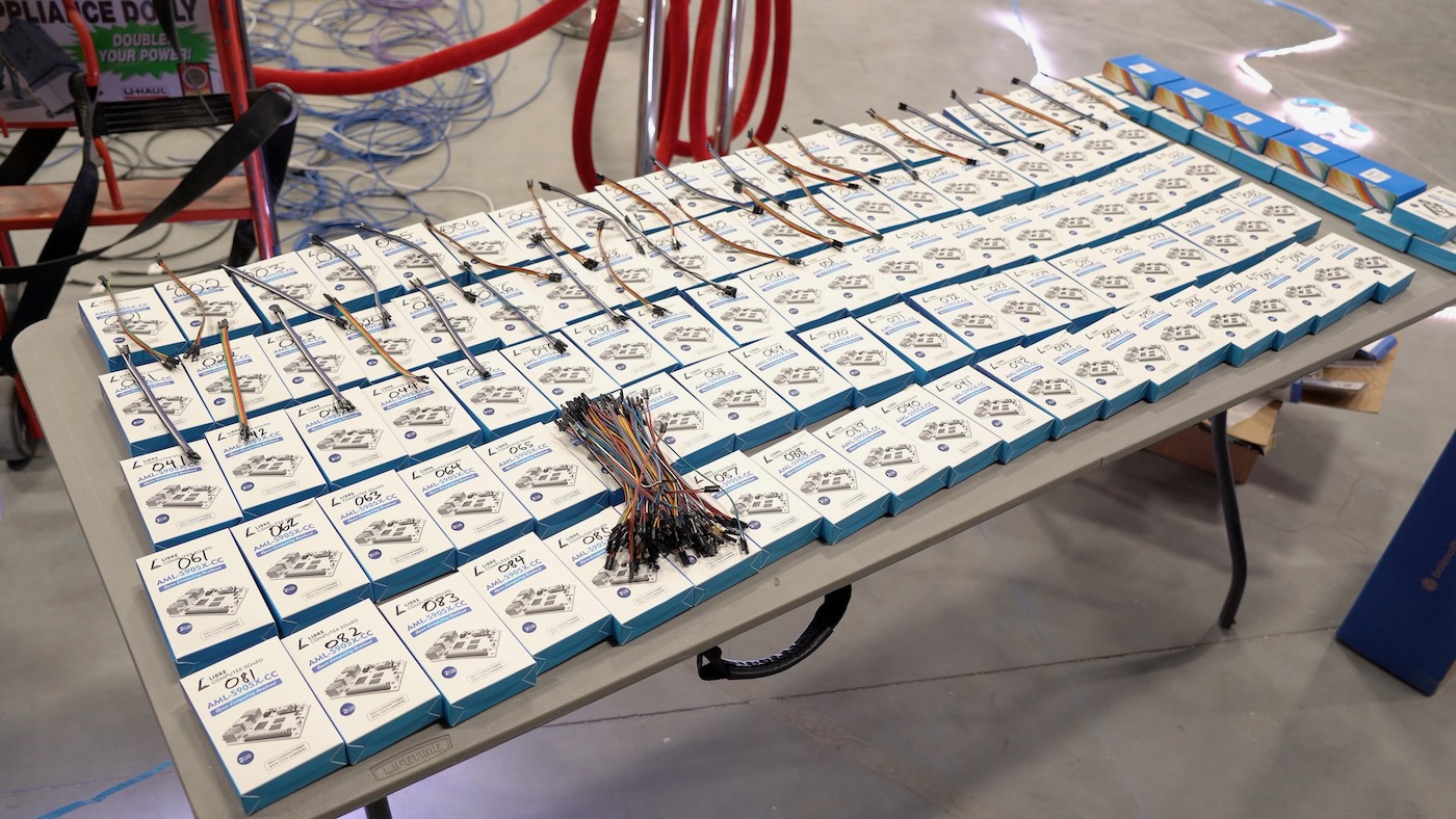
The Le Potato came in bulk 10 packs, so we were sold. We ordered 110 Potatoes ('Spuds' as I got to calling them, thinking of the 100 rooms as a 'spud farm'), and I got to programming.
Little did I know the official Raspbian image for the Le Potato didn't support interrupts when programming GPIO pins with the gpiod library. I2C worked, so I could control the relay HAT, but it looked like I was going to have to poll the GPIO pin instead of use an interrupt (so button presses could be detected for 'free' using the rising edge signal), and I didn't want to have to do that.
I found out the Le Potato Armbian release did have interrupts working, but not I2C!
After a few hours diving deep into Libre Computer's forums, I figured out how to grab a device tree overlay from their repos, and recompile it into Armbian:
wget https://raw.githubusercontent.com/libre-computer-project/libretech-wiring-tool/master/libre-computer/aml-s905x-cc/dt/i2c-ao.dts
sudo armbian-add-overlay i2c-a.dts  # this compiles the overlay into /boot/overlay-user/i2c-a.dtbo
sudo reboot
Whew. On top of the software issues, it was difficult to figure out detailed specs on the GPIO lines on the Amlogic S905X, so I had to trust it would work with the buttons and wiring we encountered on the set.
Plot twist: It didn't... sometimes.
We wound up getting a bunch of corrupt OS installs and a few completely fried boards due to static electricity buildup. Something I had not considered at all in the requirements phase were acrylic walls and carpeted floors: a static-inducing nightmare for all things electronic! 3
Would Raspberry Pis have worked better? Maybe. Should we have added a protection circuit in front of the GPIO pins? Probably. Should we have used shielded Cat5e wire instead of unshielded Cat5? 4 Definitely. But it was out of our control—miles of cable was already installed under the floor by the time we arrived on set.
LED wiring and relays
Speaking of unshielded Cat5, it was also used to hook up the LED strips instead of 5-pin 22 gauge LED wire, and initially I assumed there would just be one LED strip (maybe two) per room.
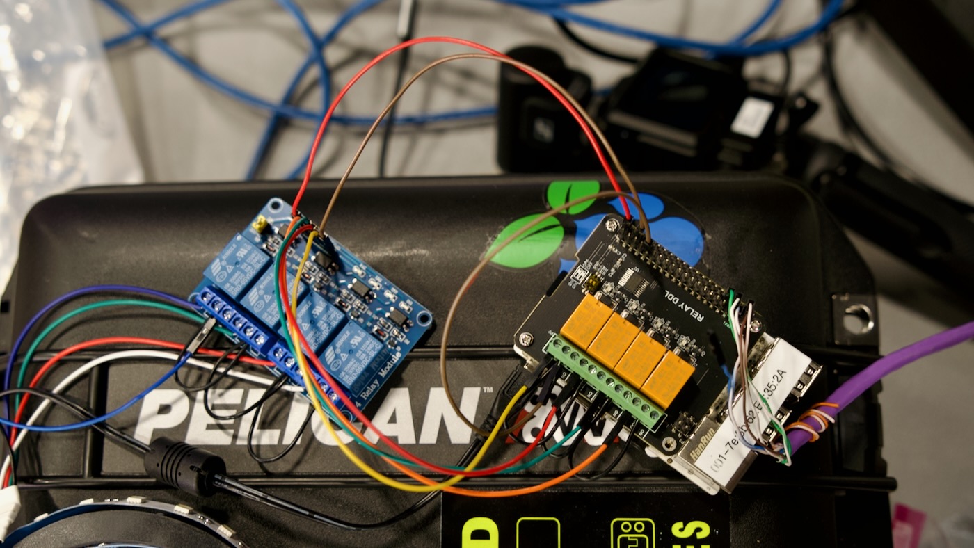
I had Chuck order these GeeekPi relay HATs, the orange ones you see on the right in the above picture. They're rated for up to 3A of DC current at 30V. When we found out there were going to be six strands of LED tape wired in parallel off the relay, I realized we needed more headroom (this was confirmed by my Dad's LED amperage tests on set). Each strand could use up to an amp at 24V... so we ended up ordering an additional set of four 10 amp relays for each room (the blue ones on the left above).
Yay for doubling the wiring per-room! I decided we'd put the 10A relays in series with the 3A relays since—at that point—the HATs were already assembled to the boards, and the software was already written and working with the Geekpi HATs.
When we arrived on set, they had some electricians work on the LED wiring, but we ran into two major problems:
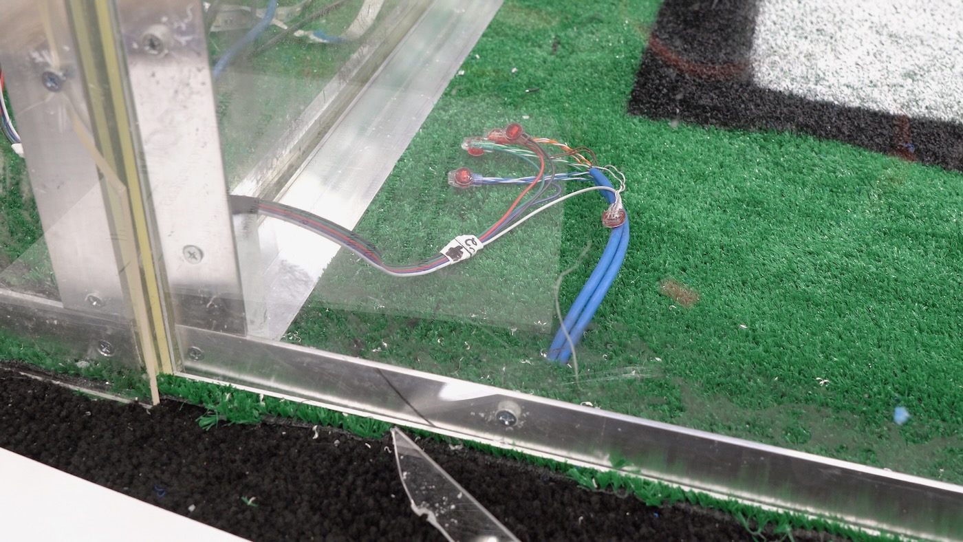
- The crimp connectors some of the electricians used to join the Cat5 from the relays into the LED tape (see above photo) weren't reliable. This was a massive headache when we had to debug strips that were out when two colors were shorted together.
- The LED tape was indoor-rated—there was no protective coating over the bare circuits on the tape. When window cleaners sprayed their window cleaner all over the acrylic... many LED strips became dead LED strips:
Eventually we debugged all the problem strips, but were forced to leave a few dead strips in place if we knew they wouldn't show up in critical camera angles. Using better cables, connections, and LED tape, we would've avoided those issues entirely.
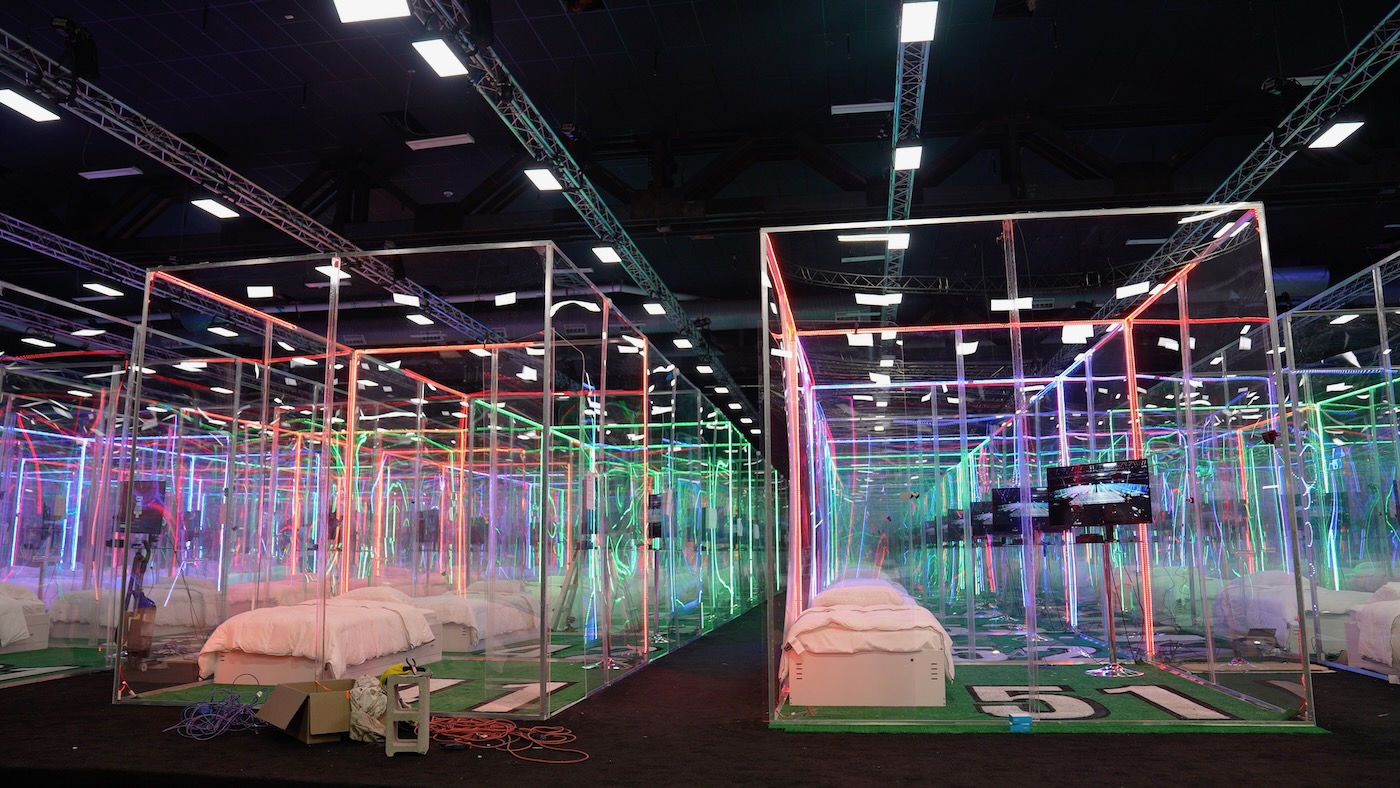
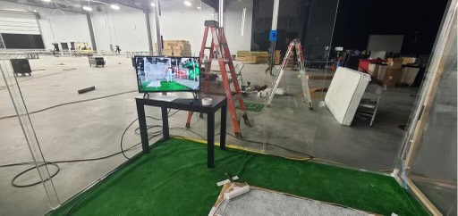
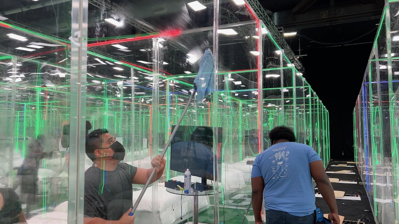
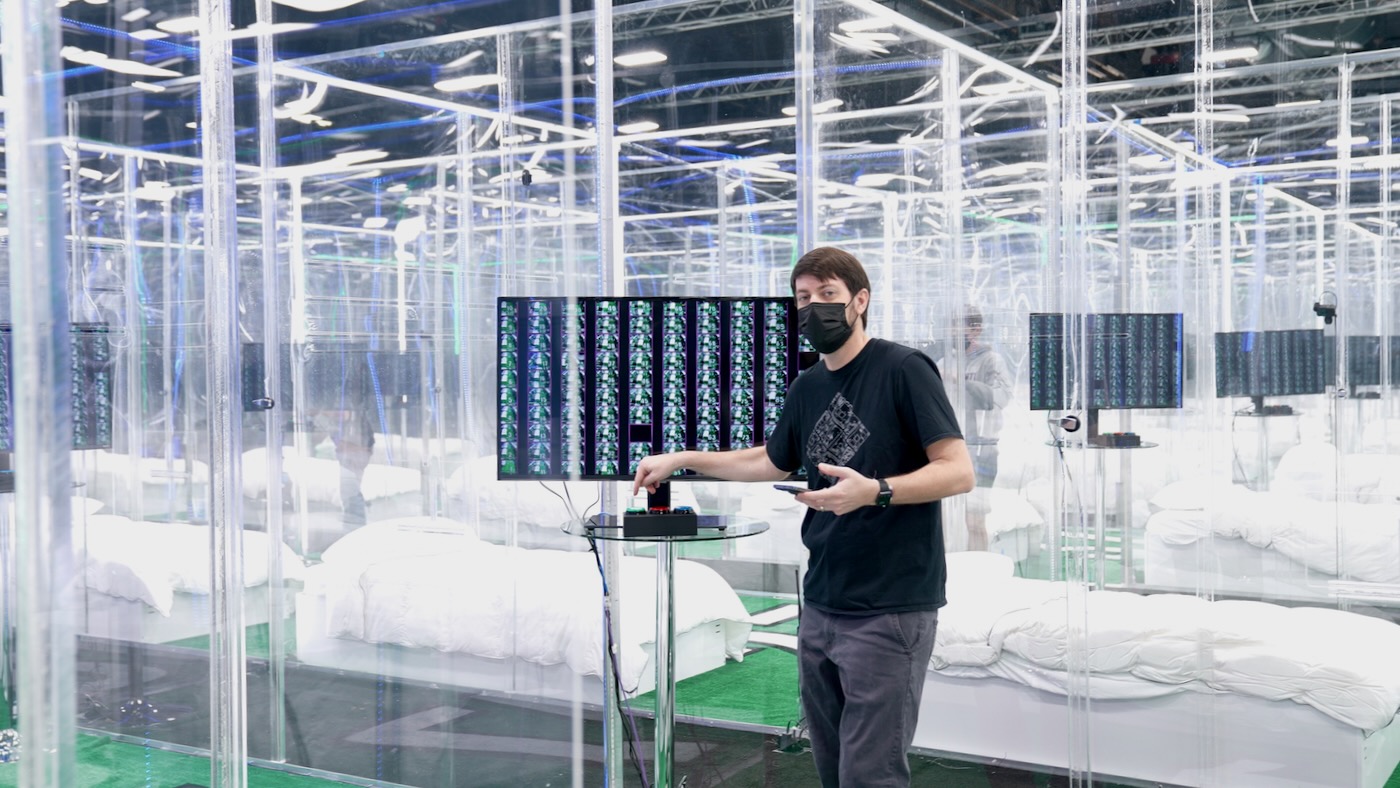
In the end, we got almost every important camera angle covered, and hearing hundreds of relays clacking on and off under the floor during our testing was extremely satisfying. It looked better than I originally envisioned once we started doing end-to-end testing (above).
Buttons
Unshielded Cat 5 caused a few issues for LEDs, but it was a nightmare for the buttons. The aged cable was a tiny bit brittle, meaning as we crimped dupont ends on the wire, it would often snap if you bent it even a little. Not fun.
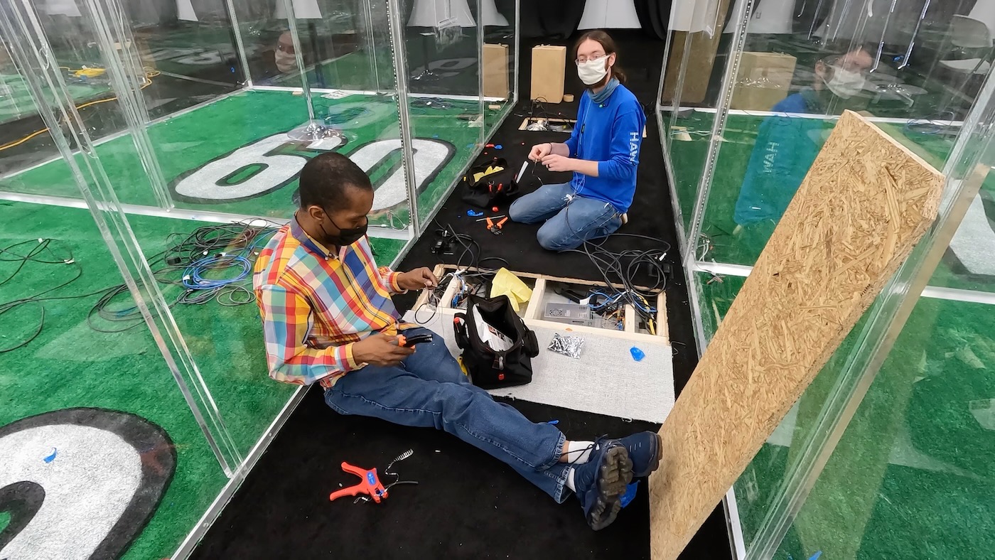
Above: Julian and Q, two local electronics/PC repair specialists, helped crimp over 600 dupont ends, all while sitting or kneeling on the floor. We ended up re-crimping maybe 50-100 for various reasons!
With everything online, the wire would act as a giant static-electricity-collecting antenna, shunting it straight through the unprotected GPIO pins into the SoC on the Le Potatoes!
If we had the time, I would've designed a custom PCB, basically a 2nd HAT. It would do the following:
- Add protection to the GPIO input pins we used for the buttons
- Add screw terminals along the edge with clear labels for each of the button inputs and grounds (so we could avoid any dupont crimps, which are... not fun at best)
But William Osman tried that for the Squid Game video, and I wasn't about to rush-order 100 custom PCBs in less than a few days!
So far I've only mentioned the wiring into the Potatoes; early on, we thought the button enclosures would be ready when we arrived... but that was never clearly communicated, so we also had to assemble 110 button boxes (100 + 10 spares, as with everything else).
For the button boxes, we premade 100 Cat 5 dongles (pictured above is just one small pile of many), and we had electricians terminate RJ45 male ends in all the rooms. That way we could just bring the built button boxes out to the room, and plug them in and go. It also facilitated quick button box replacements, which would come in handy later, when we had to customize a few boxes as individual wires in the Cat 5 cables broke!
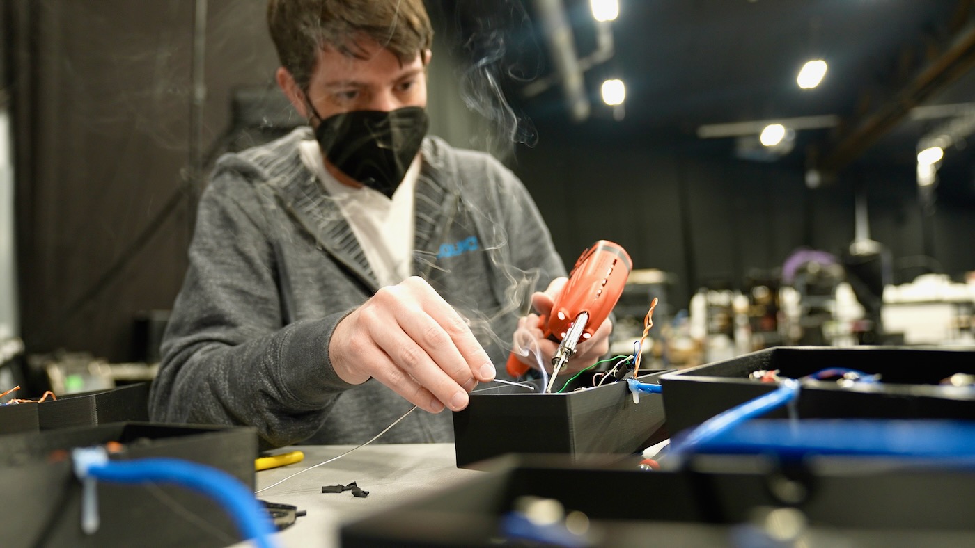
We burnt out two Weller 100W soldering guns in the course of soldering over 660 individual button connections.
We ran through a few rounds of testing, making sure every single button worked:
Unfortunately, the holes where the Potatoes were installed—and where the delicate dupont connections were housed—remained open. The camera and electrical wiring was still being run (and sometimes re-run to fix a broken cable), meaning the fragile dupont connections kept getting jostled—and one or two connections would get flaky whenever that happened.
By the end of the debugging process, the wiring bays under the floor were quite crowded:
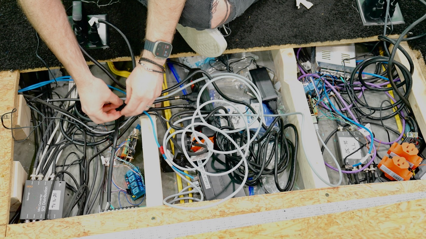
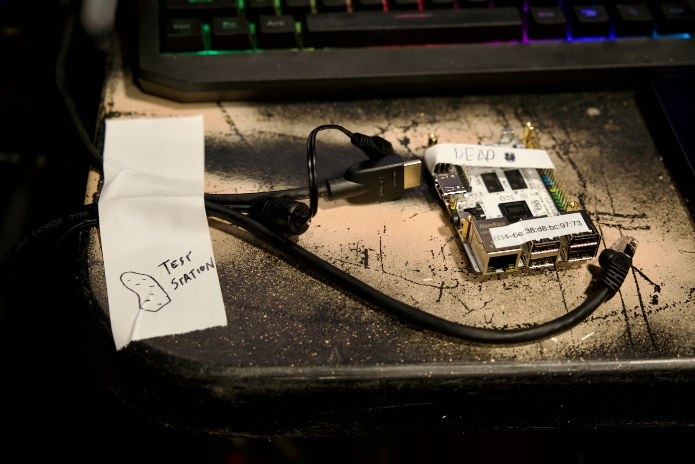
The worst problem was static, though, as we wound up having to re-flash over 40 of the Potatoes' OSes, and at least three were completely dead—we suspect from static buildup shunting straight into the SoC through unprotected GPIO inputs.
Building the Software (shell scripts, Python Flask, and SQLite)
In hindsight, the issues we ran into on the software side pale in comparison to hardware problems. Outside a few glaring bugs like never testing more than 10 rounds of voting, and relying on a function that determined the round based on the first character of a string—the software was fairly robust.
The hardest part was interpreting some of the game mechanics into controls the producers could easily grasp, and a UI that was pleasing and functional—and worked across desktop, tablet, and mobile.
On the Potatoes themselves, two scripts managed state:
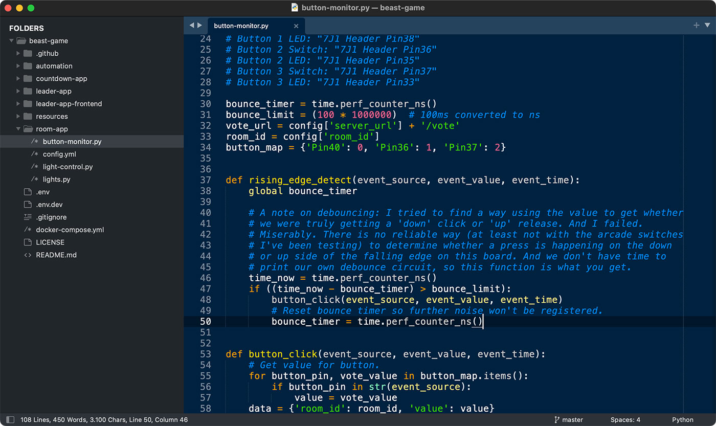
button-monitor.py: This script attached methods to interrupts on three GPIO pins, and fired off HTTP requests to the main server when button presses were detected. If an active round was set to 'live colors' mode, the script would immediately change the room color to the button color once a valid response was received (within less than 30ms).light-control.py: This script monitored a room-specific endpoint on the main server, and would adjust the room color appropriately.
Both scripts were run via systemd on boot, and one of the trickiest bits turned out to be software debounce 5, as the switches we bought had a fair bit of bounce (we'd usually get 8-12 rising edges for every time the button was depressed or released).
I wound up using a timer to count up to 1 button press per 100 ms, so if someone wanted to sit there spamming a button, it would allow them, but only at a rate of 10 presses per second:
bounce_timer = time.perf_counter_ns()
bounce_limit = (100 * 1000000)  # 100ms converted to ns

def rising_edge_detect(event_source, event_value, event_time):
    global bounce_timer
    time_now = time.perf_counter_ns()
    if ((time_now - bounce_timer) > bounce_limit):
        button_click(event_source, event_value, event_time)
        # Reset bounce timer so further noise won't be registered.
        bounce_timer = time.perf_counter_ns()
Ignore the globals and all that; remember that all this code was written in the course of a day or two. I was running and gunning—I still had to write the server-side API and design a UI for surfacing vote data and lighting control!
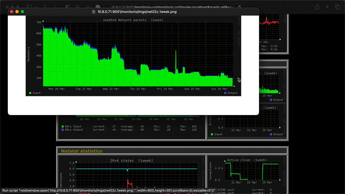
And for that, my three main concerns were ease of development, easy management, and scalability. We had to program everything assuming 100 occupied rooms, which meant 100 computers polling the API every half second for room color data, plus potentially 10 button presses per room every second. That would be a theoretical maximum of around 1,200 requests per second (it could get worse... but I couldn't program for every possibility!).
Despite building out everything to operate for 100 rooms, by the end of day one they were already down to like 80. Every day the number of rooms (and thus load on the server) decreased. With most software projects, you design for an MVP target, then scale up using live performance data as the guide. In this project, we designed for the max, and then the load got lighter as time went on—by design.
I chose SQLite for the database, mostly so I wouldn't have to manage complex database deployments, backups, and restores. File-based databases are simple and easy—if your schema is simple and easy.
Running on an 11th-gen NUC with fast NVMe storage, we could get at least 700 requests per second, which was good enough for me—I told the producers to try to not encourage spamming the buttons in the first day, when all rooms were online. Besides, the 80+ crowd probably couldn't sustain 10 button presses per second that long, right?
To get the confidence in our load capacity, I learned how to use lua scripting with wrk to hammer the server with real-world button and LED data.
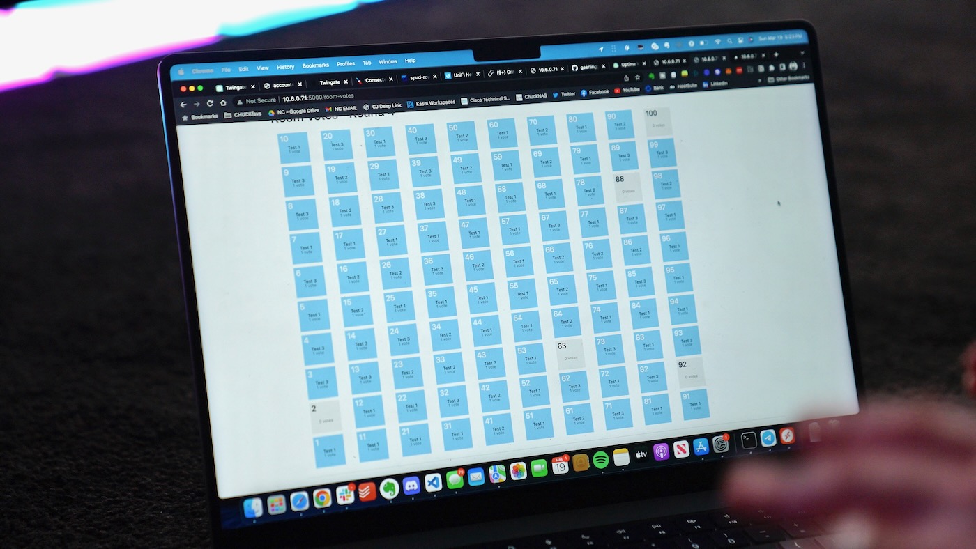
On set, I was pleased to see—after a few small tweaks—the UI I had designed was easy enough for the producers and the production techs who were debugging LED issues to pick up immediately.
I'm currently seeking approval from the MrBeast team to publish the open source 'beast-challenge' software I wrote for the project. I'll post a link here if I can get approval!Thebeast-challengerepository is public, now!
I let Network Chuck and his team handle the front-end design for the big screen though; it's been a few years since I did much JS dev work, and I wanted to focus on the backend and hardware. The giant display behind MrBeast below showed real-time vote data (polling the backend API), and was coded up by a developer on Chuck's team:
Managing Change
Speaking of things Network Chuck took care of—he set up all the networking infrastructure, from the three Cisco switches, to a Unifi AP, to a pfSense firewall, and the two NUCs we ran the 'farmer' server app on.

I don't know when he'll have a video out from the experience—like me, he had so much footage to go through, and the project went in so many different directions. But it would be fascinating to see his side of the story, from purchasing and assembling the Potatoes (and transporting everything!), to working on the frontend displays, to networking... our skills complemented each other well on this project.
The network was rock solid, besides one port that was somehow toasted on the brand new Cisco switch (my guess is somehow the cable got a charge in it and fried the port).
And Chuck set up Twingate on the NUCs so I could remote in and manage everything from anywhere.
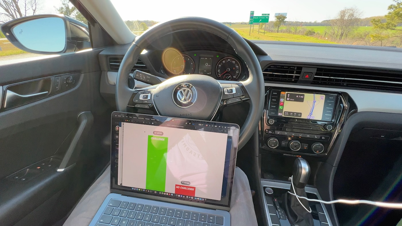
This came in handy many times, from late night fixes from the hotel, to an emergency hotfix from the highway in my rental car on the way back to the airport in the middle of the shoot (pictured above)!
I made sure every aspect of the system was managed via Ansible, and could be managed from the farmer servers themselves—that way if I wound up without Internet (like on the flight home), someone else could still reboot the whole system if all hell broke loose (luckily, it did not!).
Besides persistent issues caused by the static electricity (participants were wearing socks, on carpet, in rooms made of acrylic... really the perfect storm for static), and a couple dumb bugs caused by coding far beyond my normal waking hours, the system worked well through the week-long shoot, and helped make one of MrBeast's biggest videos for 2023!
What I'd do differently
A lot.
Was the 100-node SBC architecture the best? Probably not. Hindsight is a wonderful thing; if we had more time, I think I would:
- Build a custom PCB for each room, with protection circuits for all the button inputs, built-in relays, and screw terminals for everything.
- Design an enclosure for the kit that would protect it from the harsh construction environment.
- Use a socketed connection on the PCB for something like an ESP32 or Pico with Ethernet—or use CANBUS or RS485 and avoid Ethernet entirely. (Or, if using an SBC, build the board as a singular HAT).
- Make sure we have one fully-built room with the working prototype, before full-scale set construction began
Unfortunately, reality rarely offers the time to fully flesh out a system before you start building it...
Watch How I almost broke MrBeast's 1-100 video for even more detail.
Check out the code used for the challenge: geerlingguy/beast-challenge.
If you have other suggestions, feel free to comment below!
-
In hindsight, we should've had a switch in each row (maybe two!), to reduce the amount of wiring under the floor, as well as the length of the longest home runs—the Ethernet cable between our main switch and room 10 was about 325 ft (100 meters), which is the rated limit for gigabit Ethernet over Cat 5! ↩︎
-
We literally called Raspberry Pi and asked if there was any way possible to acquire 100 of Raspberry Pi 1, 2, 3, or 4 within a week's time (even on loan, and at almost any price), and they said every single unit they produced was already accounted for. Early 2023 was truly peak shortage for the Pi, and they were managing their supplies to single unit quantities. ↩︎
-
The Le Potatoes weren't the only electronics getting hammered... we had issues with the GoPros as well, once the protective film was torn off all the acrylic! They would flake out and power off, or send garbled HDMI output from time to time, until we got the static discharge under control (well, as much as we could). ↩︎
-
That's right, not Cat5e! They had to buy a ton, quickly, and the local supplier they used only had old unshielded Cat5 wire in bulk. Not only was this cable slightly brittle—which would cause us problems with termination to both LED wires and GPIO pins, it was unshielded, making it much less suitable for 3.3v button signaling. Watch the video linked at the top of the post for more on the problems that caused! ↩︎
-
For debounce, in addition to watching the video that goes along with this blog post (where I demonstrate bounce in the analog realm!), read this excellent piece by Jack Ganssle: A Guide to Debouncing. ↩︎
Comments
That’s absolutely incredible Jeff, thanks for the breakdown! Hopefully the Beast team give you approval to publish the software (and maybe even Chuck’s frontend??) - would be epic to read through!
Definitely! I'm letting them take time on that, but I'm hopeful we'll get that software out the door.
Any Updates?? Super curious
Still no... I will ping them again today!
When does the mr beast video come out ? :D i'm curious :D
MrBeast's video was out in May I think, and my video on this is out today! Check out the link in the first line of the blog post :)
It's already out
https://youtu.be/FM7Z-Xq8Drc
Hi Jeff, great video and blog.
I think the main thing I’d have done differently is using some kind of DMX LED tape decoder. Perhaps this (but other variations exist) https://www.solidapollo.com/120V-AC-DMX-to-RGB-LED-Decoder.html
It would be less faffy than dealing with power supplies, relays and the various connections for the sake of a slightly less convenient software integration. Also it would allow for more advanced effects, especially if it was pixel tape and the driver supported it.
Not a bad option, though pricey at 100x for each room!
Doing all of this in 2 weeks is nothing short of incredible!
And with no colon on top of it all!
You know what they say, "no colon, still rollin!"
Yeah, I think SBCs and dupont connections in open bays where lots of contractor activity is going on is not a good idea. Enclosures, even if you had to buy a lot of tupperware containers, would probably have reduced the number of issues a bit.
I commented on YouTube also, but...
PLCs with 24V IO modules. 4 or 5 8+8 I+O modules, plus slim relays for the LEDs... One plc per row of boxes, driven by modbus over ethernet.
Or alternatively, just modbus IO blocks for every 2 rooms.
Industrial stuff will spit on your ESD (because it's isolated and/or protected) and your debounce ('cause it's slow enough). Having the hardware itself be more bulletproof saves soo much time, because chasing hardware bugs takes walking time, while chasing software bugs doesn't.
Its always cool seeing insight into how such a big production was made possible behind the scenes
Okay. Out of budget PLCs would have been. Not by much, and I think you went over anyway... But I can see why it wasn't considered at least
Hi Jeff, nice video and good read! Thanks for sharing. Is the whole video setup (with the GoPro’s) done by MrBeast’s team themself? I would be so interested in that setup.
dude, this is just awesome. i can't tell you enough how much i enjoy this sort of project behind the scenes and this SCRATCHED my itch perfectly, thank you :) coordinating different teams must have been like hell in this time limited situation electricians, cleaner ladies spraying your leds (lmao btw), all the networking guys managing kilometers of cat5, programming the potatoes... btw how did you program the potatoes, did you ssh into them individually?
Ansible! We have some simple playbooks that managed deployments, updates, backups, and even hot swap failover.
Heh, I'm wrapping up an electronics project now feeling the vibe of your video.
I wouldn't ditch the ethernet, the other protocols have their own issues and the galvanic isolation of ethernet probably saved you more than you know vs can/485 in that bad of an environment lol.
I kept wondering why didn't you put the sbcs in the button box? Nice short run for your signal wires then and ready access. Too many cables coming out of the box for the video people? I bet they asked for it to be wireless first lol.
Heh in your "if I had time and money version" POE would have been a sweet solution for the button box and sbc, the LEDs are left as an exercise for the reader.
Also for debounce, a pattern I really like and have used in the pi and others is use interrupts, on going low edge trigger. When triggered disable (mask) the interrupt for that pin and set a timer or a flag for something in the main loop that will wait your bounce time then re enable the interrupt on that pin.
Everyone seems to wait until the pin has stopped bouncing before acting which can be quite slow as you've seen.
The only thing to watch for is if your interrupt source doesn't tell you which pin fired. Because if you trigger your isr on change by the time you get around to polling the pins to see which one actually changed the pin can be back high again. It'll happen way way more frequently that you'd expect btw. You're like man there's gonna be like 25 instructions between the pin going low and me reading the pins there's no way it'll bounce the fast. Yes, yes it will.
This is specifically an issue on esp32 that you can work around in a gloriously ugly fashion by creating an array of functions that call your real isr with the pin number as an argument. You can attach any function as an isr for a pin, but there's not an easy way for an isr on there to know which pin change led to it being called. I believe the old PIC had a nice register you could hit and it'd tell you how you got there.
(If you didn't have global's I wouldn't trust you, nobod human is that good who still gets stuff done 🤣)
Very interesting read, thanks for directing me here!
Wouldn't it have helped to ground the acrylic to an earth pin?
What would your hardware design be to protect your GPIOs?
Since acrylic is an insulator, grounding just one point on it would only ground that one point, insulated from the rest. The only way to effectively ground an entire panel would be to cover it with a thin metal film.
You can add protective diodes to the GPIOs to send the static surges to ground.
I would have gone wireless networking for sure, MQTT is a lightweight network messaging protocol used in lots of smart home devices like switches and sensors. You could have the lights controlled directly by your potato (or an ESP32) and then send voting data over MQTT. That kind of thing is done commonly in industrial IoT and 100 devices on a network really isn't that many. Particularly if you spread it out over like 4 routers.
I was having the same thought and curious how it would work in a setting like this.
Zigbee switches are pretty cheap, $20 for an off the shelf one, making your own is probably even cheaper. Were the static issues amplified because of all the cables? If it was wireless, would the static be less of an issue?
Great write-up. I wonder if ESP-MESH would have provided sufficient latency. I wonder why they didn't just buy project boxes - they come in that size and it had to have taken forever to 3D print so many.