A PTP Wall Clock is impractical and a little too precise
After seeing Oliver Ettlin's 39C3 presentation Excuse me, what precise time is It?, I wanted to replicate the PTP (Precision Time Protocol) clock he used live to demonstrate PTP clock sync:

I pinged him on LinkedIn inquiring about the build (I wasn't the only one!), and shortly thereafter, he published Gemini2350/ptp-wallclock, a repository with rough instructions for the build, and his C++ application to display PTP time (if available on the network) on a set of two LED matrix displays, using a Raspberry Pi.
A Pi is useful because it meets the two requirements for a PTP Clock:
- It's easy to interface with LED matrix displays (via GPIO and a HAT)
- It's Broadcom NIC has PTP hardware timestamping capabilities.
I wanted to rebuild his clock for my own amusement, and to have a visual aid for upcoming videos about PTP. And I was successful!
In this post, I'll detail the hardware used, the physical build, and how to get from a fresh Pi OS installation to displaying PTP time on a 128x32 RGB LED Matrix!
I also published a YouTube video of the process, in case you want a more visual guide:
Required Hardware
The required hardware costs around $120-150, depending on what part of the AI bubble we're in:
- Raspberry Pi 4 model B (the Pi 5 doesn't yet work with the RGB matrix)
- Adafruit RGB Matrix HAT + RTC for Raspberry Pi
- Waveshare 64x32 pixel LED Matrix Panel (x2)
- Adafruit 5V 4A power supply (or equivalent)
- 32GB microSD card
Any Pi 4 should work fine; you don't need a lot of RAM.
And if it isn't obvious, you also need a PTP grandmaster somewhere on your network, which should be broadcasting to the standard PTP multicast IPv4 address, 224.0.1.129. You could also have multiple PTP grandmasters, allowing the Pi to use PTP's Best Master Clock Algorithm (BMCA) to select the best time source.
Hardware Setup
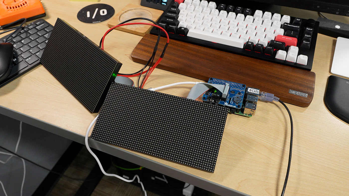
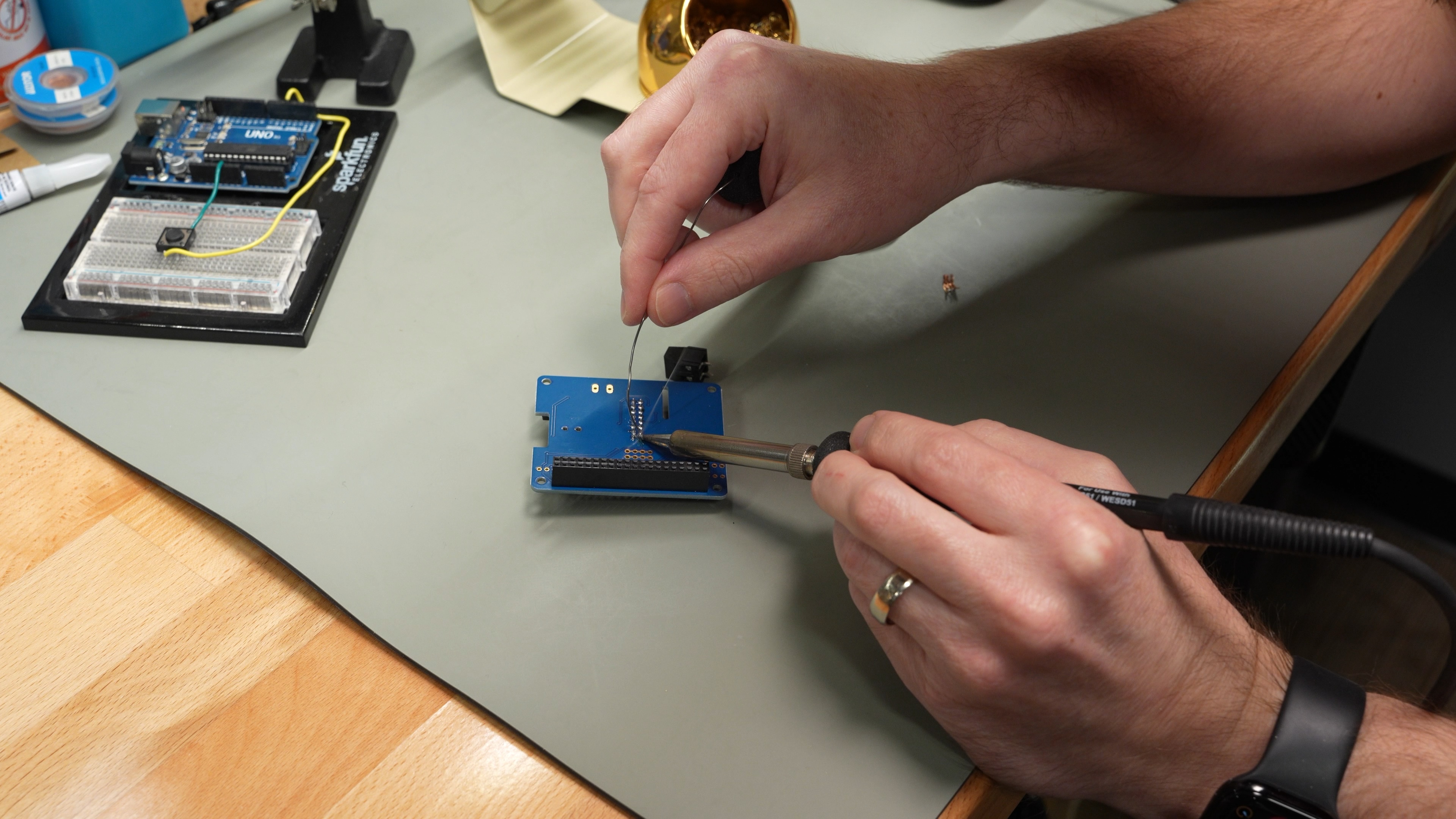
The Adafruit RGB Matrix HAT requires some soldering. There's 2x20 female pin header that fits on the Pi's GPIO header, a ribbon cable connector on the top side, and a 5V DC power output screw terminal header to supply power to the two LED matrices.
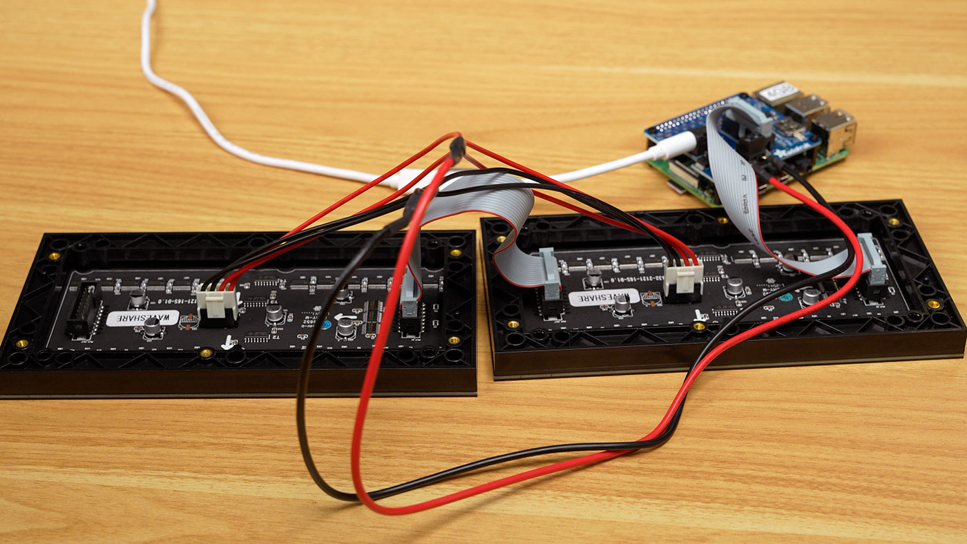
Once that's done, it's a matter of plugging cables supplied with the two Waveshare LED Matrix Panels into the header on the Adafruit HAT. One ribbon cable goes from the HAT to the 'right' LED matrix (when viewed from the front). Then the right matrix plugs into the left matrix using the other ribbon cable.
The power cable is already split for two matrix displays, so plug the 4-pin plugs into the power inputs, and screw the screw terminals into the positive and negative screw terminals on the HAT. They will be halfway-out, so... don't short anything across them. Alternatively, snip the ends off and strip a little wire to screw into the screw terminals directly.
A picture is worth a thousand words:
Plugged into the 5V DC input jack (5.5mm x 2.5mm, center positive) is a 5V 4A power supply.
In the picture above I'm using a Werewolf VFLEX adapter with a Raspberry Pi USB-C power supply, but a dedicated 5V 4A supply is best, to prevent voltage drop when driving the display (which causes flickering).
Software Setup
Assuming you have a fresh install of Raspberry Pi OS on your microSD card, there are a few stages to the software setup.
The first step is to configure the Pi for optimal performance refreshing the LED matrix. Disable general CPU core scheduling (so threads can better pin themselves to a single core), and disable the built-in audio output:
# Edit `/boot/firmware/cmdline.txt` and put this at the end of the line:
isolcpus=3

# Disable audio by switching the parameter to 'off' in `/boot/firmware/config.txt`:
dtparam=audio=off
Blacklist the snd_bcm2835 kernel module:
cat <<EOF | sudo tee /etc/modprobe.d/blacklist-rgb-matrix.conf
blacklist snd_bcm2835
EOF

sudo update-initramfs -u
Reboot the Pi to apply the changes above:
sudo reboot
After the reboot, make sure the audio module is not loaded (this command should return nothing):
lsmod | grep snd_bcm2835
Now it's time to install the RGB LED Matrix library, to allow the Pi to interface with the display through it's GPIO pins:
# Install RGB LED matrix library.
cd ~/Downloads
git clone https://github.com/hzeller/rpi-rgb-led-matrix
cd rpi-rgb-led-matrix
make
pip install .
The make and pip install . commands will both take a while, especially on the older Pi 4's anemic CPU. Once compilation is finished, test to make sure the LED matrix is working:
# Make sure the RGB LED matrix is working with a demo (Conway's Game of Life).
make -C examples-api-use
sudo examples-api-use/demo -D7 --led-rows=32 --led-cols=128 --led-chain=1 --led-gpio-mapping="adafruit-hat"
If that worked, then you're golden! If not, you either have a hardware or a software issue you'll need to debug.
Now it's time to set up the PTP Wallclock application. First, copy over the font the application uses, from the RGB LED Matrix project you cloned earlier (make sure you're in that project's directory still):
# Copy over the font used by the PTP wallclock app.
sudo mkdir -p /usr/share/fonts/rpi-rgb-led-matrix
sudo cp fonts/6x13B.bdf /usr/share/fonts/rpi-rgb-led-matrix/
Finally, it's time to build the PTP Wallclock app:
# Clone the PTP wallclock app.
cd ~/Downloads
git clone https://github.com/Gemini2350/ptp-wallclock.git
cd ptp-wallclock
Until PR #8 and PR #11 are merged, you need to apply those patches to the project to make it work correctly:
curl -sL https://github.com/Gemini2350/ptp-wallclock/pull/8.patch | git apply -
curl -sL https://github.com/Gemini2350/ptp-wallclock/pull/11.patch | git apply -
To compile the app, copy the ptp-clock.cpp file into the rpi-rgb-led-matrix directory, and then run this command in there:
# Compile the PTP wallclock app.
g++ -O2 -std=c++17 ptp-clock.cpp -o ptp-clock \
    -I./include -I./bindings \
    -L./lib -lrgbmatrix -lpthread
Now, you can run the following command to start the compiled ptp-clock app:
$ sudo ./ptp-clock
Listening for PTP Messages...
If you don't see any time on the LED matrix, here are some PTP debugging steps:
- Do you see PTP traffic on the network from the Pi running
ptp-clock? Installtcpdumpand runsudo tcpdump -i eth0 -nn -v port 319 or port 320. You should see some messages with timestamping information. - Look at the
msg typefield in the output of the abovetcpdumpcommand. If you only seesync msgmessages, and nofollow up msgmessages, the PTP server may be configured in one-step mode. On your PTP server, check thattwoStepFlagis set to1in the ptp4l configuration.
I posted an issue in the ptp-wallclock repository with some of my own debugging steps, which may be helpful if you're still having issues: Can't get PTP time to display on my network.
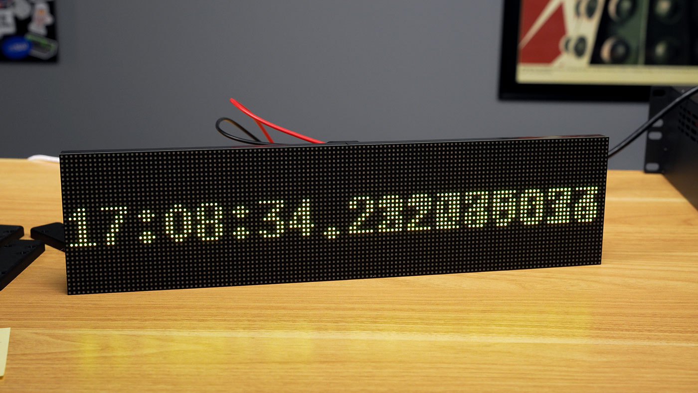
But if everything's working correctly, you should see the current PTP time:
NOTE: Until this PR is merged, you might need to apply a patch to the
ptp-clock.cppfile before compiling. If you get an error, or no output, and you know PTP is working on your network, run these commands:cd ~/Downloads/ptp-wallclock curl -L https://patch-diff.githubusercontent.com/raw/Gemini2350/ptp-wallclock/pull/8.patch | git apply -v cp ptp-clock.cpp ../rpi-rgb-led-matrix cd ../rpi-rgb-led-matrix g++ -O2 -std=c++17 ptp-clock.cpp -o ptp-clock \ -I./include -I./bindings \ -L./lib -lrgbmatrix -lpthread
3D Printed bracket / stand
It's a bit messy without any support, and the two halves of the display don't stay together well, unless you attach them to something. There are four magnetic screws for each display, so if you attached them to a flat metal surface, you could get them to line up that way.
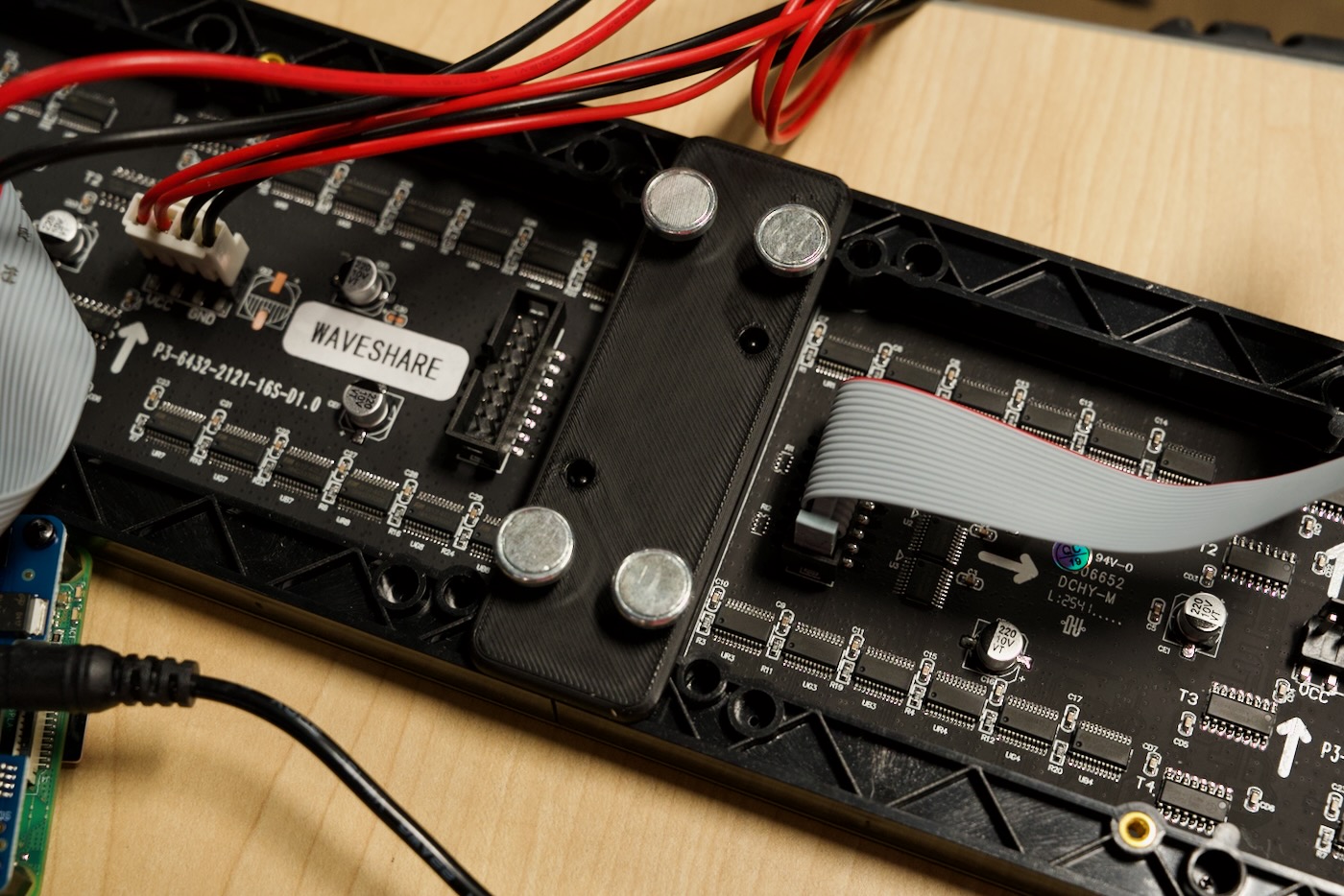
I designed this 3D printable bracket, which attaches the two displays with a tiny bit of wiggle room, to account for manufacturing variances. I put it up on Printables if you want to replicate my build: PTP Wall Clock Bracket (Waveshare RGB Matrix connector).
In the future I may also tie in the Raspberry Pi somehow, maybe in a desk stand base. But my mounting bracket keeps the magnetic screws at the same height as the others, so you could mount this to a fridge or other ferrous surface, with the Pi dangling below. Or tucked away behind with a hole cut in the metal for the data and power cables.
Conclusion
Now that I have this nice PTP time display, I need to figure out why my GPS-derived time is driving +/- a few seconds from UTC every couple days. I think the Intel i226 NIC I'm using is handling the PPS time input incorrectly, and I'll keep working on that in this issue. I may also switch to another Pi time server, as the i226 driver has been generally frustrating.
I'd like to give a huge thanks to Oliver Ettlin for sharing his work—and for his excellent 39C3 presentation on PTP! Watch it if you have any interest in PTP or network timing.
And if you want to build your own PTP wall clock, I hope this blog post has helped :)
Comments