As the son of a radio engineer, I've seen my share of radio towers. From small, rural AM and FM towers to urban 'constellation' towers serving dozens or even hundreds of services, there's a lot more than meets the eye.
My Dad and I visited the so-called 'FM Supertower' in St. Louis, MO twice now, to explore the tower and the supporting infrastructure below. Both of these visits are documented on our Geerling Engineering YouTube channel:
But in this blog post, I'll guide you through some of the highlights, and maybe you'll learn a bit more about how talk and music radio makes its way to your car speakers—at least here in the US—using a technology less than 100 years old and rife with technological change.
From IP to RF
The audio for FM radio broadcast comes to the transmitter site via a variety of methods. We won't deal with the origination of audio today—radio studios, IP audio, and STL links are topics for another day—but most facilities, this one included, have redundant audio paths to make sure a brief Internet interruption doesn't bring down the feed.
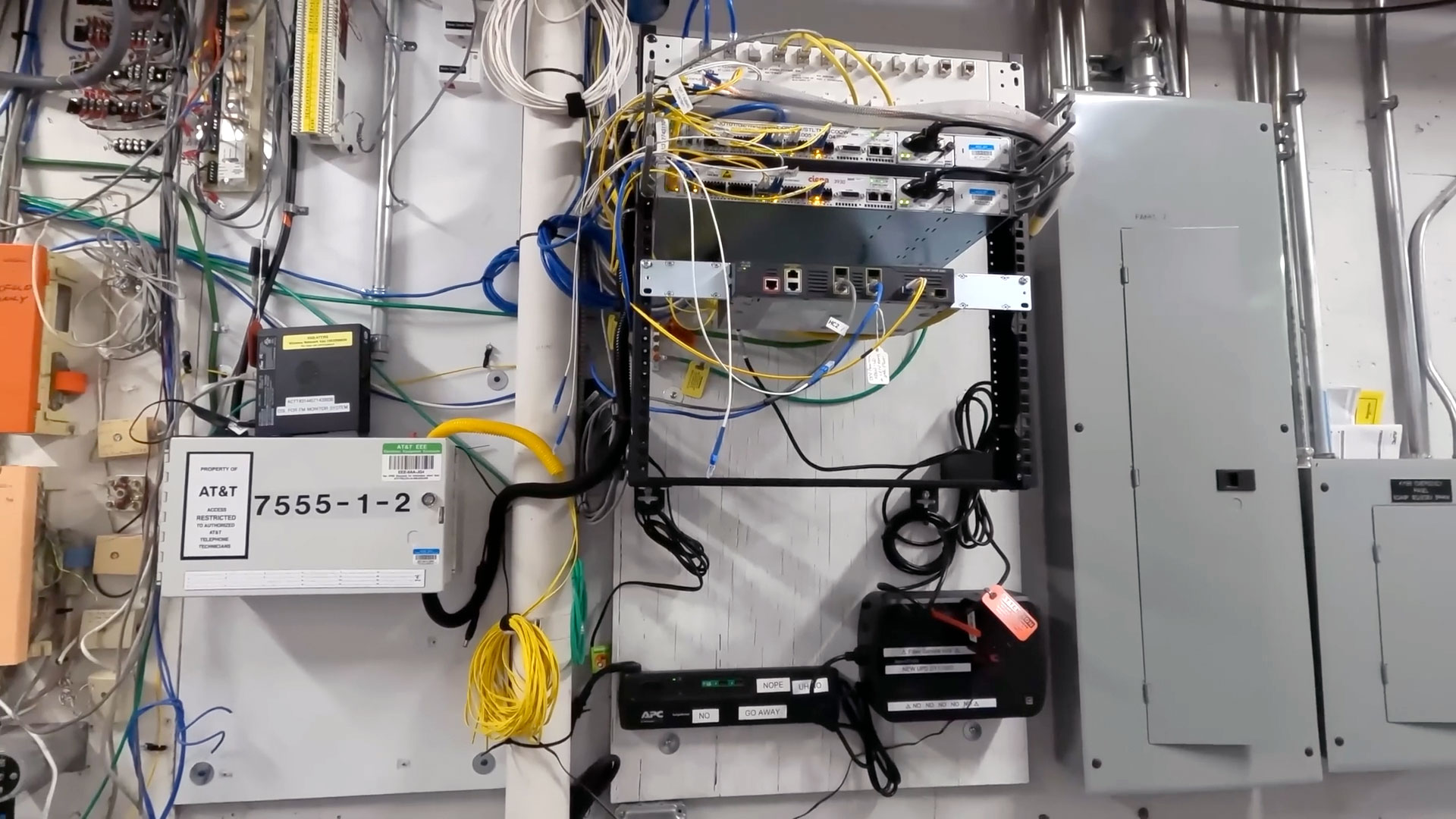
Most of the stations at the facility get their audio over the Internet, via fiber. Some still have other Internet links, like cable or even T1 lines, but fiber gives a lot more bandwidth for a lot less cost these days.
The Internet is piped into the transmitter room over a transmitter building LAN, and from there it gets processed into two signals: IP for 'HD Radio', which is a digital signal, and analog for traditional radio (here in the US, widespread digital radio adoption is still minimal).
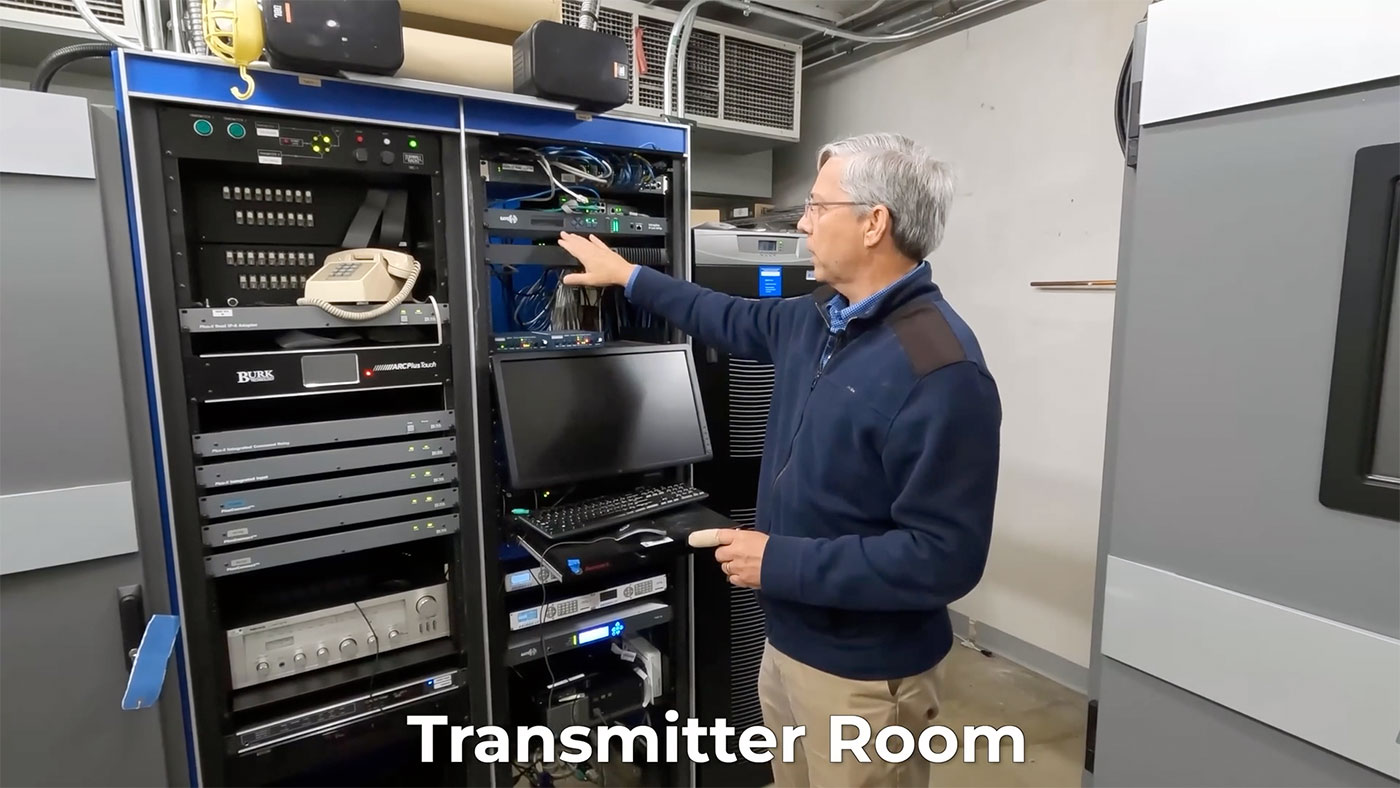
Until the final run to the antenna system, the digital and analog signal paths are separated. First, we'll deal with analog, since the power requirement is many times greater:
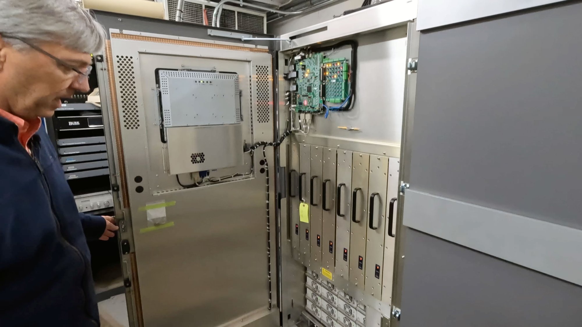
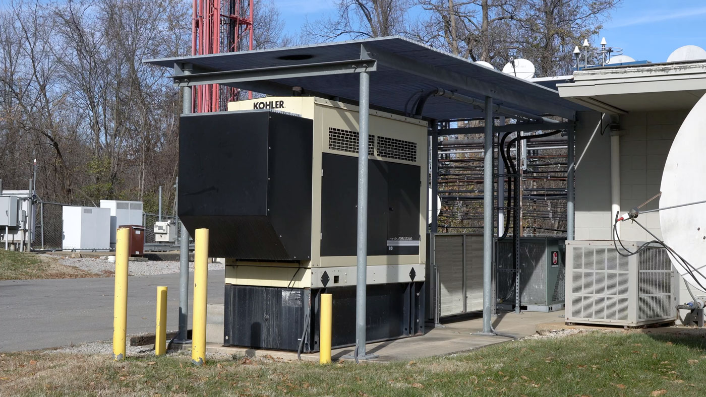
Pictured here is a Nautel NV40 FM transmitter, with an exciter and 16 RF modules, powered by 40 independent power supplies. In the back of the transmitter room, 480 volt building power is stepped down to the power requirements for this transmitter, but it's too much power to be provided by the in-room UPS, which is only able to keep the other audio equipment up until the giant diesel generators can spin up (in the case of a power outage):
Inside the analog transmitter, audio and other information is 'excited' into a frequency-modulated signal, and then the RF modules (all those vertical units in the middle) combine to output a 30,000 watt RF signal that gets sent out via 3" copper hardline coax.
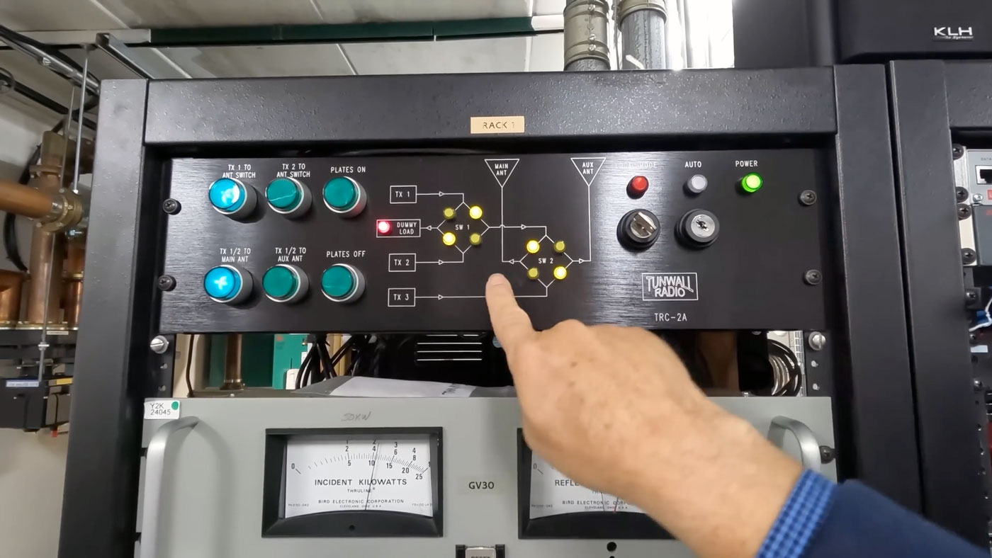
The coax gets routed into a switcher, alongside another coax line from the backup analog transmitter, and that switcher has two outputs: one to the antenna, and the other to this 50,000 watt dummy load:
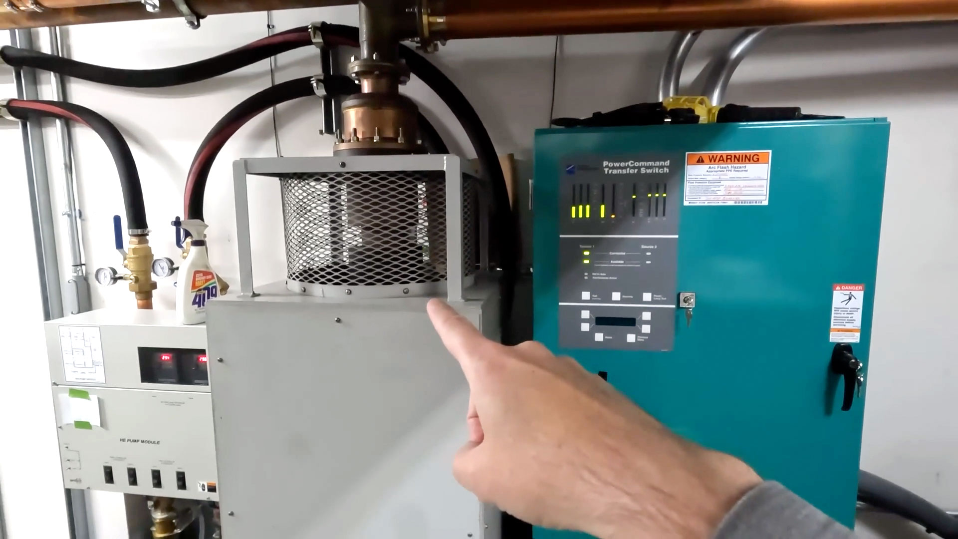
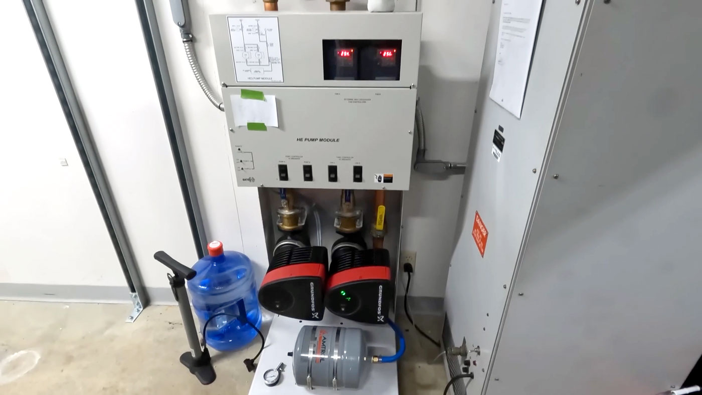
Since we're talking tens of thousands of watts, heat is a major concern, so most transmitters have pretty substantial air cooling systems—though one of the transmitters at this facility is water cooled, with redundant pumps and a bit of extra monitoring should things go south:
Jumping over to the digital HD radio signal, it is transmitted on two 'side-channels' that surround the main FM signal in the middle of the radio station's allocated FM channel, in this case 102.5 MHz:
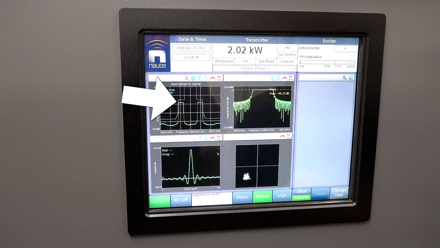
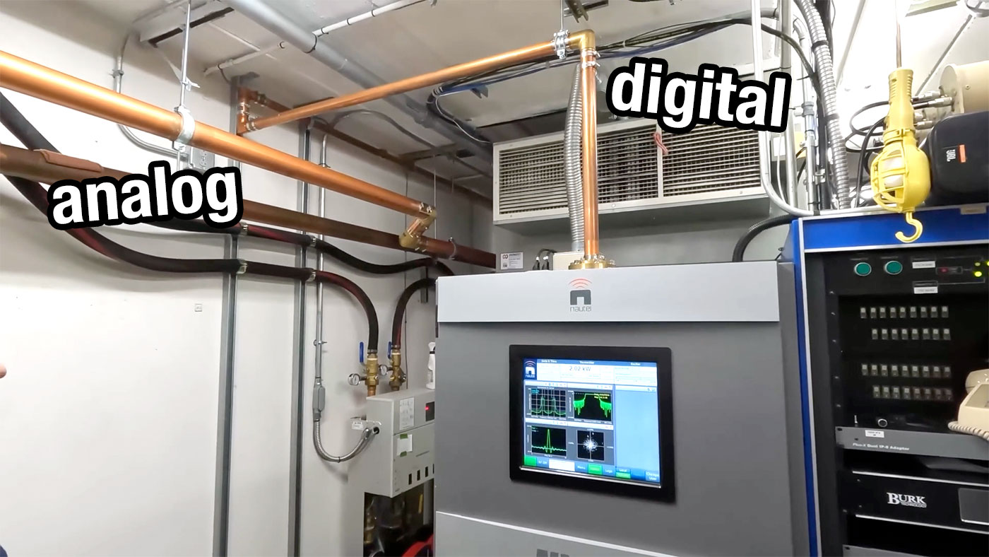
Since the digital signal uses 1's and 0's to transmit data, and doesn't need the fine resolution of the FM signal to send a song over the air, the actual signal power is much lower (around 2 kW vs the analog 30 kW signal)—illustrated by the comparatively tiny coax line coming out of the top of the transmitter:
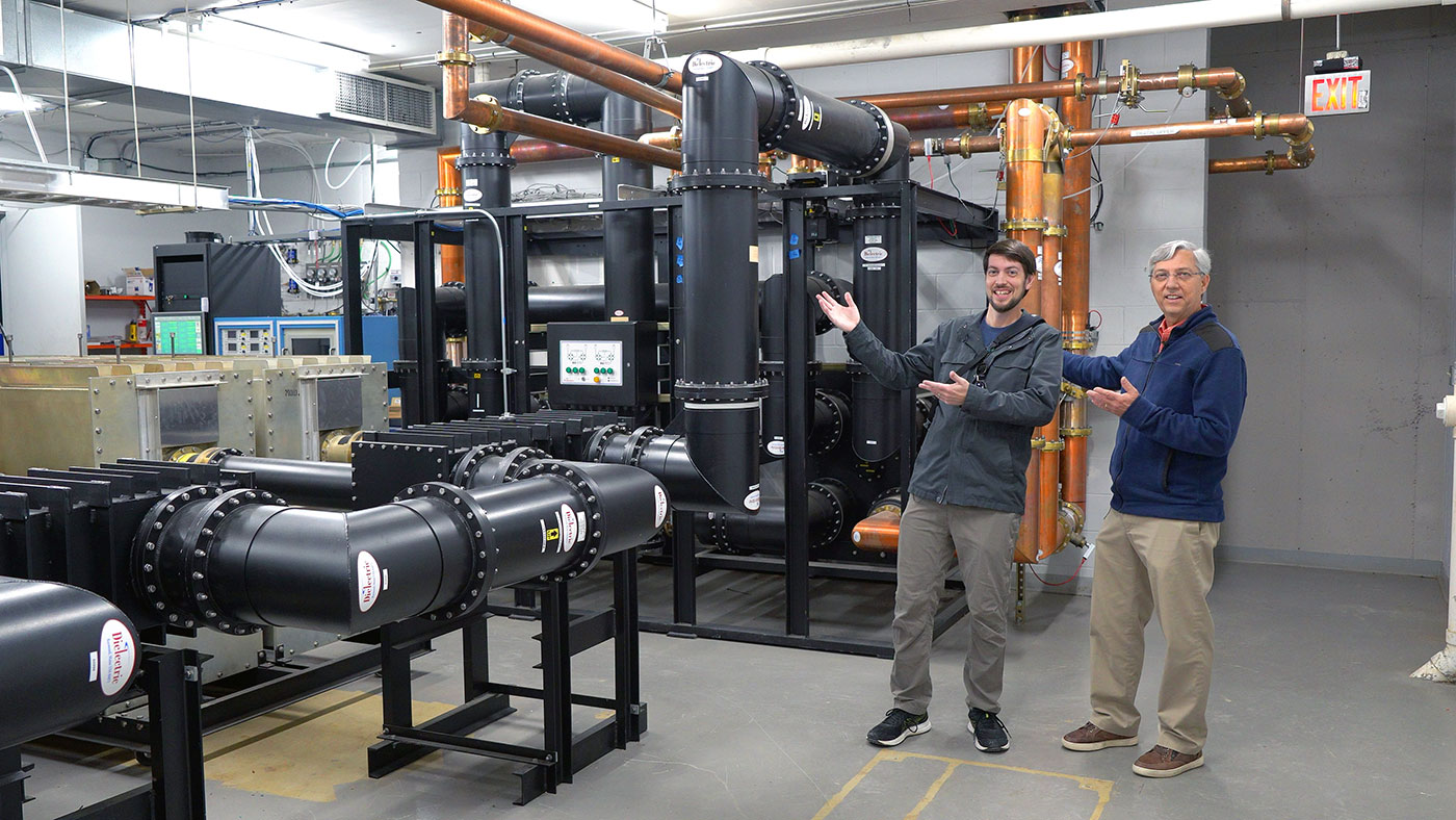
The active analog transmitter output and the digital output coax head down to the 'combiner room', where at this tower site ten FM radio station signals are combined into two outputs. The stations average around 30 kW of RF each, and so the equipment is understandably industrial in size.
Combining for Efficiency
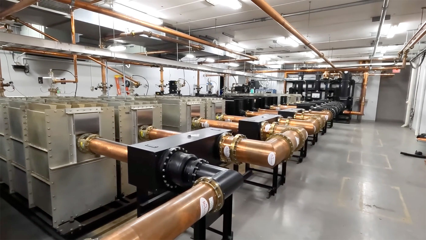
This room takes each transmitter's output (and in most cases, a separate HD radio transmitter's output), then combines that signal into the main feeder that goes up the tower to the 8-bay dual-antenna system at the top.
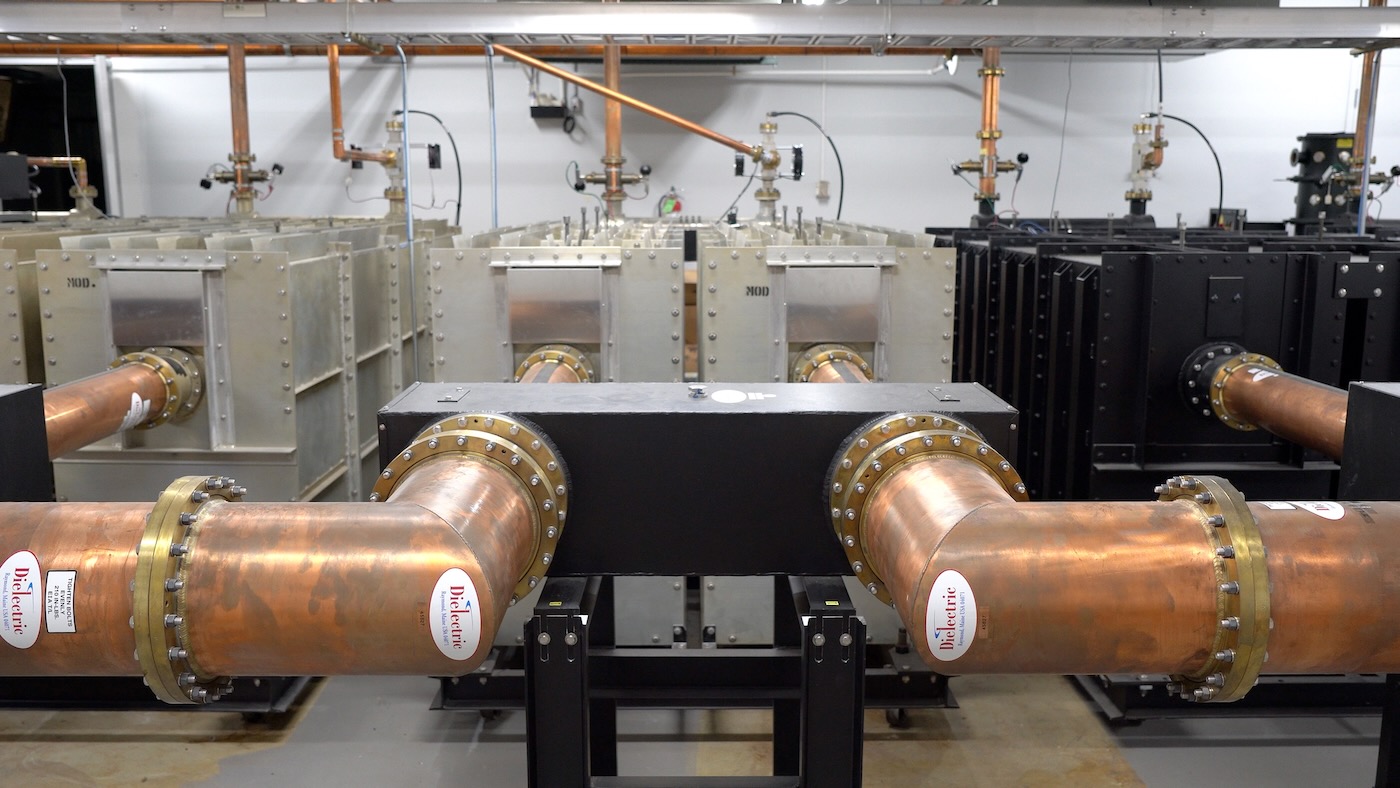
Looking more closely at a single combiner, you can see the 7" coax coming in from the left, entering the RF combiner, then exiting on the right towards the next combiner.
These units must perform a bit of magic, combining multiple RF signals relatively near each other on the FM band, into one roughly 300,000 W FM signal at the end, output in a 9" coax line that gets switched into a tuned 8-bay antenna 1115 ft (340 m) above the earth.
Going up the Tower
An obvious question at this point: how does hardline copper go up to the top of a tower—which is allowed to move somewhat with the guidance of guy-wires—without breaking or causing a short?
Well, there is special engineering in both the coax and in the way it connects to the tower.
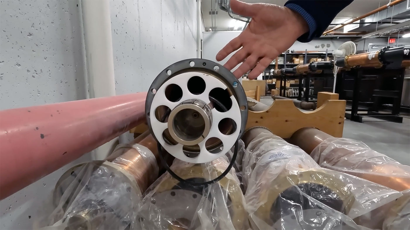
First, looking at a spare length of coax, you can see it's the same basic principle as the coax cable you might use for a household cable TV or cable modem: there's a center conductor for the RF signal, then an insulator (in this case, teflon spacers that center the conductor in the middle, while allowing Nitrogenated air to pass through (providing insulation between inner and outer conductors), then an outer conductor that is grounded to the tower system.
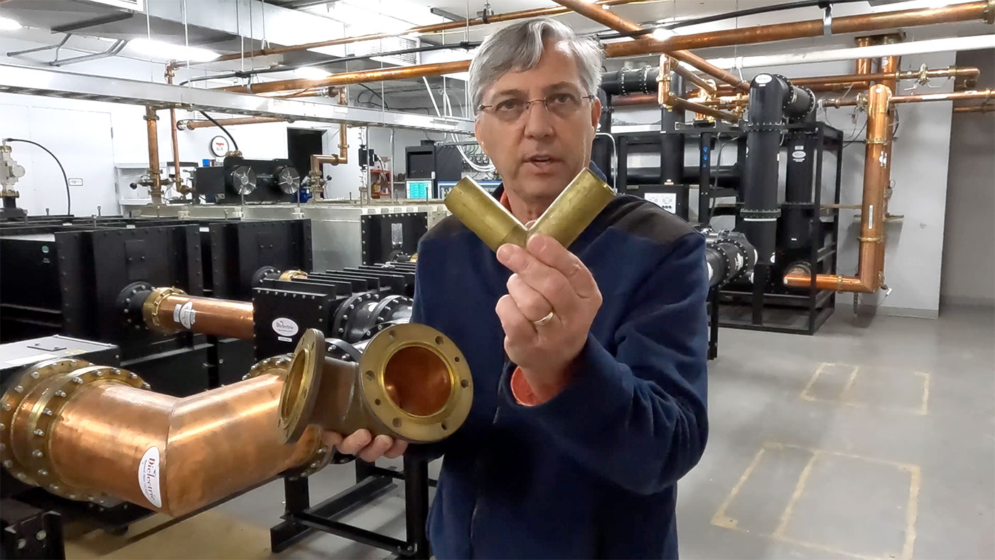
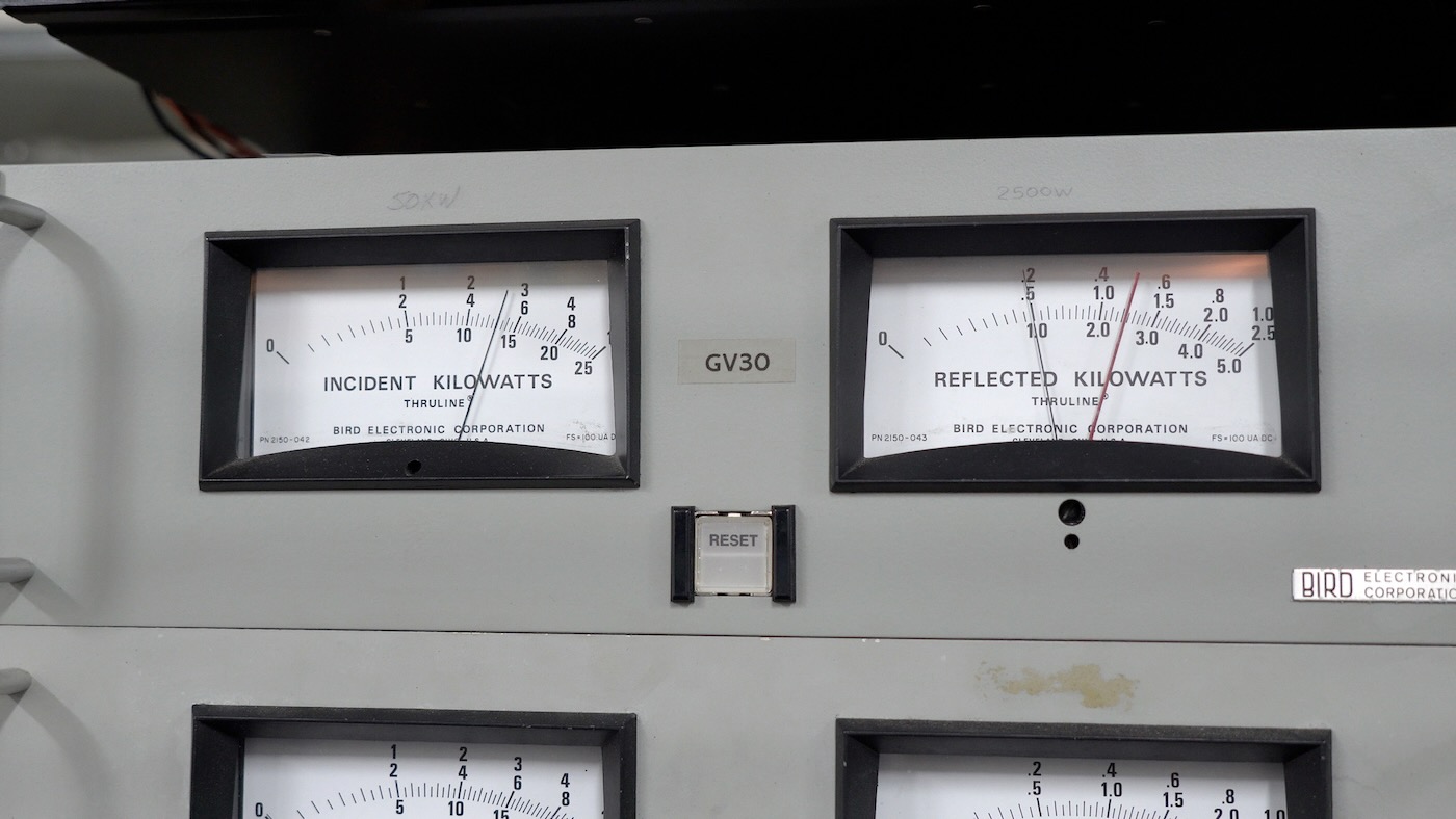
There are losses in every connection, especially in the 90-degree bends, which are engineered specifically for the 50 ohm impedance required by the antenna system. But those losses are accounted for, and in RF, the 'reflected power' (that is directed back into the transmitters) is also monitored to prevent reflected energy in the system from damaging a station's transmitter:
Once the hard coax line leaves the building, it takes a final 90° bend up into the tower itself:
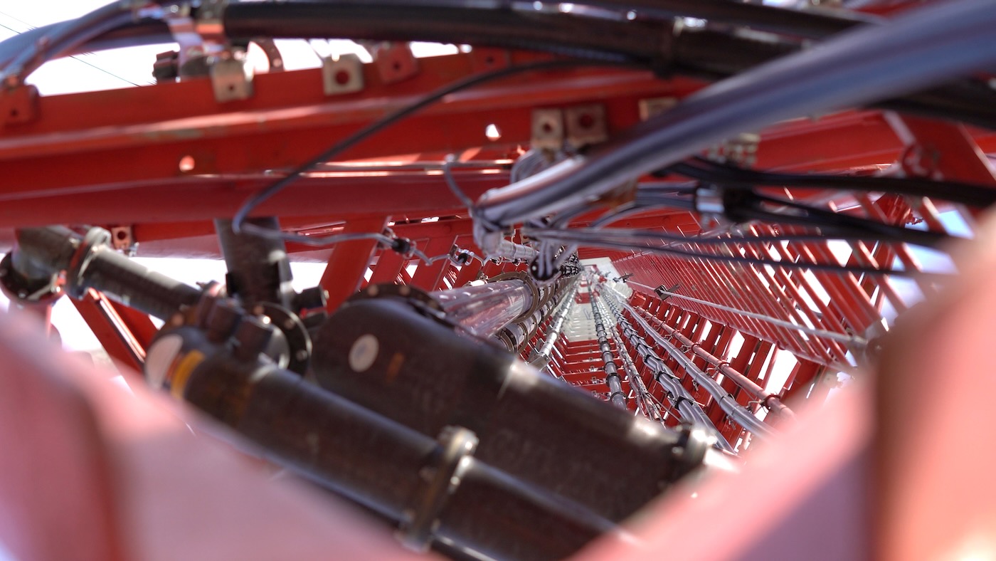
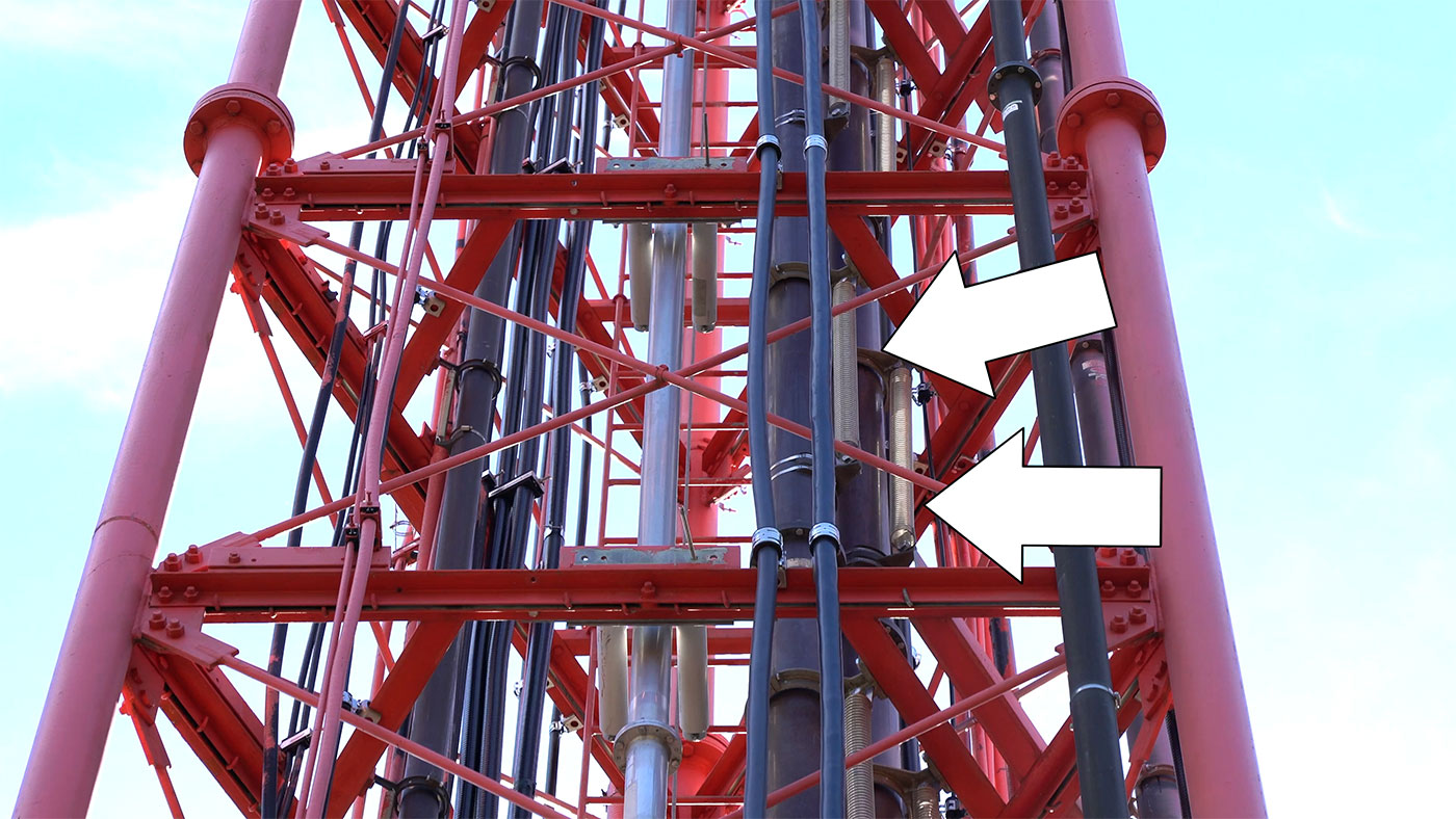
But with over a thousand feet of copper, and many connection points between, things like thermal expansion have to be accounted for, so every connection point uses a flexible hanger, mostly using large springs to allow for vertical and horizontal movement within the run:
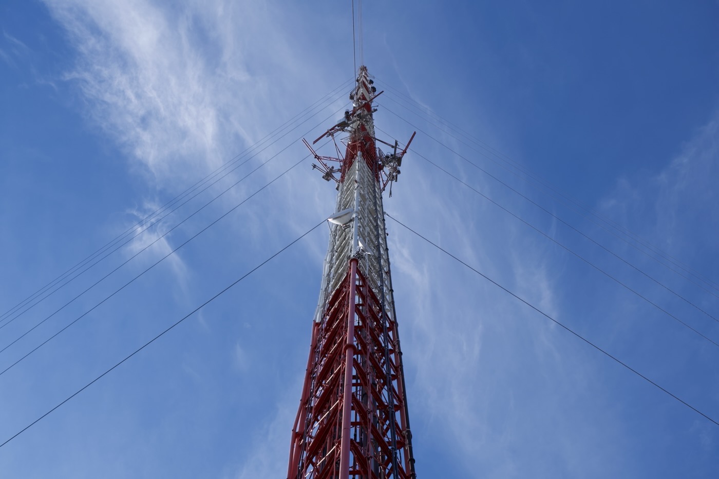
Directing RF efficiently—and safely!
Once you get the signal up to the top of the tower, you have to convert the RF energy into a broadcast signal for maximum geographical coverage.
And for FM signals, it's important to get the antenna system as high as possible, and to try to direct the signal for maximum reach, without wasting a lot of energy towards the sky, where few people would benefit, or beaming a ton of RF straight down towards the ground in one spot, drawing the ire of the FCC.
My Dad explained that a single antenna would not be very directional, and the radio station's rated power is based on how much coverage you'd get with a single-bay antenna. But if you combine four antennas and tune them well, you can get a much more 'directional' signal:
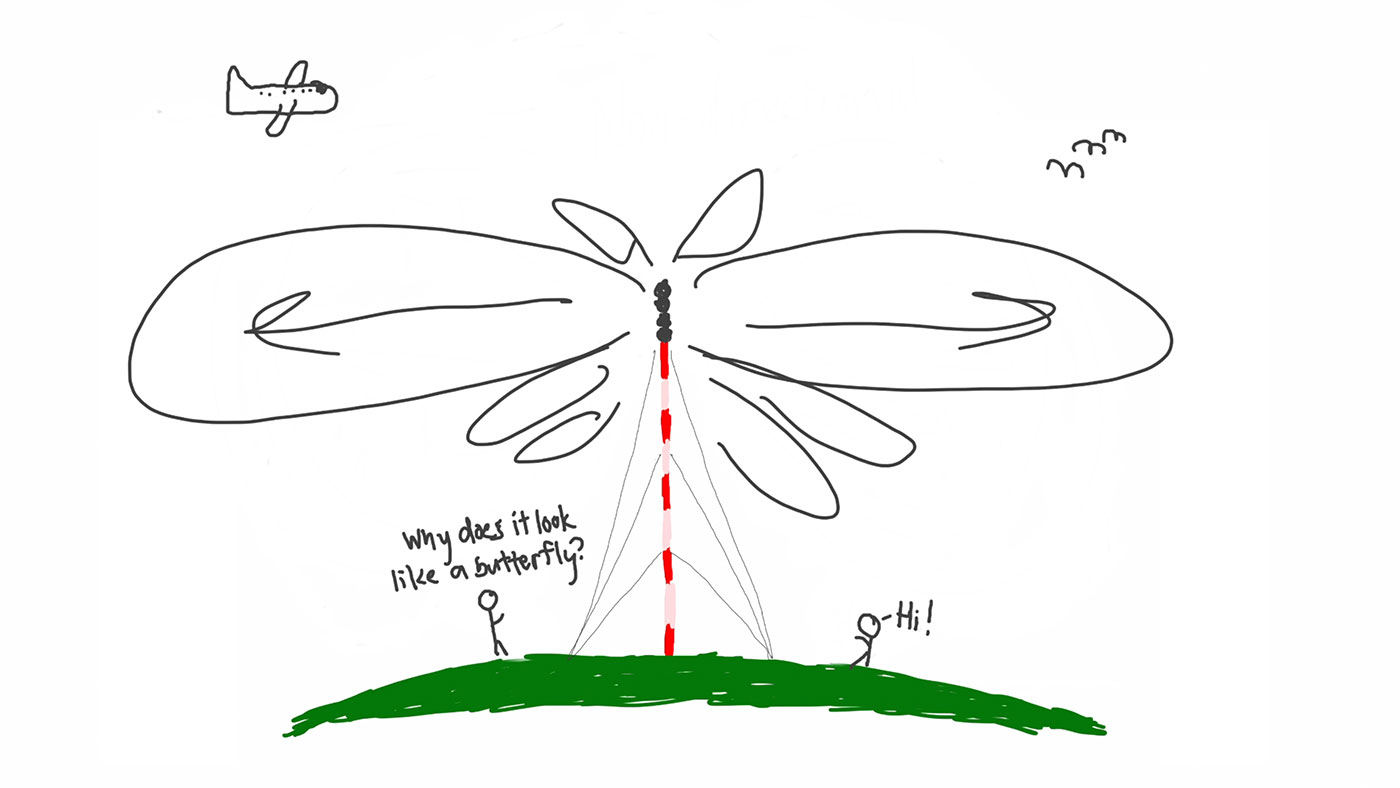
Playing with the physical characteristics of that antenna, you can even direct the beam of RF, and optimize the coverage you get for a given amount of RF, so in the broadcast industry, the term 'ERP' (Effective Radiated Power) is used.
Thus, the 'supertower' site broadcasts roughly 1 MW (1,000,000 Watts) ERP, even though the signal coming into the antenna system is closer to 330,000 Watts.
That's why station KYKY (Y98 FM) in St. Louis is rated by the FCC as a '90 kW' station, even though the transmitter outputs around 30 kW of radiated power.
Other odds and ends
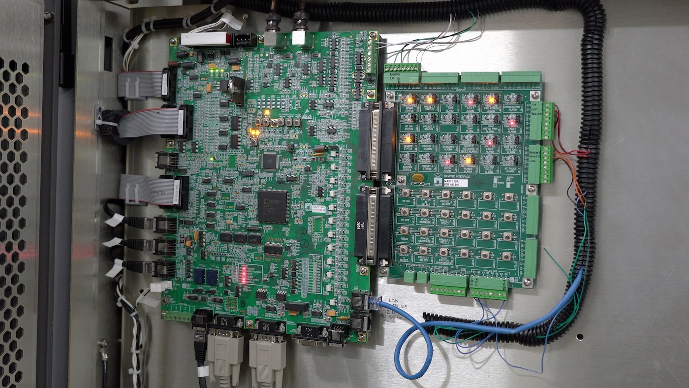
There are a lot of other things this blog post doesn't cover that we discussed in the two videos, like ice protection, lightning protection, remote control (can you spot the FPGA in the above picture?), safety lighting, backup power, auxiliary services, and other questions we got after posting the first video.
I'd encourage you to watch both videos if anything in this post piqued your interest!
Right now I'm recovering from a surgery, but in the new year, my Dad and I hope to visit an AM tower and a TV tower, to show some of the major differences in handling those very different types of signals!
Subscribe to our Geerling Engineering channel so you don't miss any of our upcoming videos!
Comments
Super interesting, thanks for the great writeup and videos!
how far does the 1 million watts FM Supertower go in rural flat land?
How large of a radio antenna would be needed to detect this signal from 1ly?